Coil built-in semiactive vibration absorber with closed structure

A closed structure, built-in technology, applied in the direction of shock absorber, shock absorber-spring combination, shock absorber, etc., can solve the problem of natural frequency-current characteristics The actual state of the magnetic circuit is different from the calibration state, and the control program cannot execute the frequency, etc., so as to improve the work efficiency and applicability, improve the vibration absorption ability, and reduce the center of gravity.

Inactive Publication Date: 2012-02-29
HARBIN ENG UNIV
View PDF5 Cites 15 Cited by
  • Summary
  • Abstract
  • Description
  • Claims
  • Application Information

AI Technical Summary

Problems solved by technology

[0007] 1. In the structure of the whole machine, axis 1 is used as both a supporting structure and a guiding role, so it is only suitable for a position with good verticality, and cannot resist swinging or horizontal use;
[0008] 2. The way shaft 1 protrudes from both ends is not conducive to sealing. In the marine environment, it is greatly affected by salt spray, and the internal components are easy to corrode;
[0009] 3. The external design of the spring 3 makes the balance position and preload state of the spring change every time it is installed. The actual state of the toothed magnetic circuit between the internal stator and the mover is different from the calibrated state, resulting in control The program cannot execute the corresponding frequency
Experiments show that the natural frequency-current characteristics of the electric semi-active vibration absorber with the traditional structure are greatly affected by the installation pretightening force of the spring pressure plates 2 at both ends, and the working characteristics have strong nonlinearity, which has caused serious problems to the working process of the control system. bad influence

Method used


Image

  • Coil built-in semiactive vibration absorber with closed structure
  • Coil built-in semiactive vibration absorber with closed structure
  • Coil built-in semiactive vibration absorber with closed structure

Examples


Embodiment Construction

[0020] The present invention is described in more detail below in conjunction with accompanying drawing example:

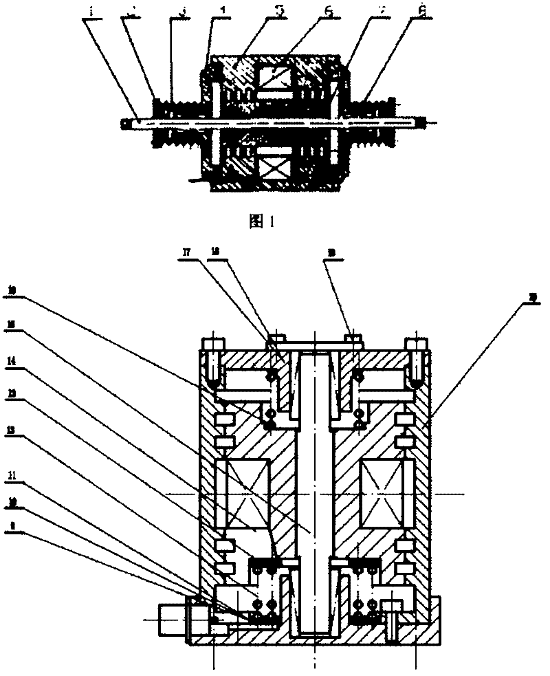
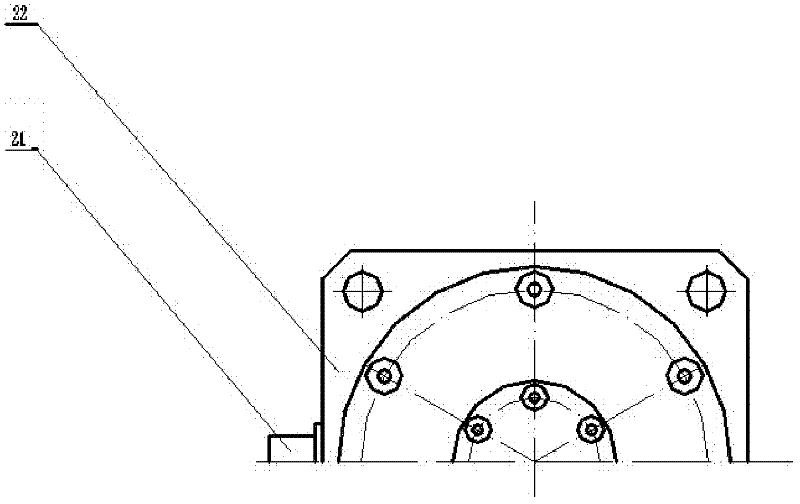
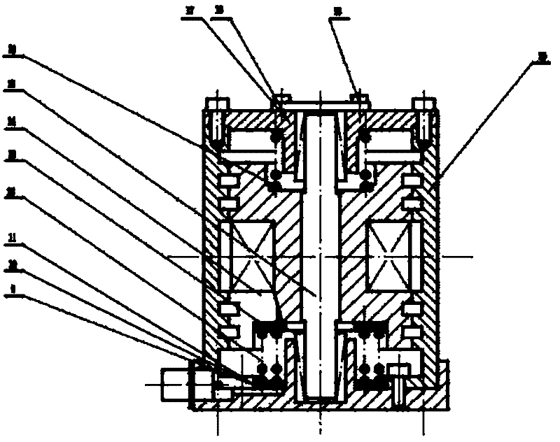
[0021] 1-3, the structure includes base 22, outer shell 20, armature assembly 14, shaft 15, ferromagnetic coil embedded in armature assembly 14, spring 16, bolts, upper cover 17 and other parts. The outer casing 20, the base 22, the upper cover 17 and the shaft 15 constitute the fixed part of the shock absorber. The armature assembly 14 is sleeved on the shaft and accommodated inside the housing. The springs and pressure plates at both ends of the armature assembly 14 are also enclosed inside the housing. Once the spring preload is adjusted, there is no need to change it. When installing, just fix the packaged shock absorber on the controlled part through the screw hole of the base, so that The influence of the installation preload of the spring on the control characteristics is eliminated.

[0022] The characteristics of each part are mainly reflected in:

[0...


PUM


Abstract

The invention aims to provide a coil built-in semiactive vibration absorber with a closed structure. The coil built-in semiactive vibration absorber comprises an outer shell, a base, a shaft, an armature, a spring, an upper cover and a ferromagnetic coil, wherein the outer shell is connected with the base; the upper cover is arranged on the outer shell; the armature is arranged in the outer shell and is connected with the outer shell; the shaft passes through the armature and is arranged on the base; a spring for positioning is arranged between the shaft and the armature; the outer shell, the base and the upper cover form the closed structure; an annular slot is formed on the central outer wall of the armature; and the ferromagnetic coil is arranged in the annular slot. A base supporting mode replaces a shaft supporting mode, so the gravity center is reduced, the supporting area is increased, the installation stability is improved, and the anti-swing capacity of the supporting mode is about within 45 degrees. A coil winding is combined with an active cell mass block, so the mass of a stator is reduced relatively and the mass of an active cell is increased; therefore, the volume of the whole vibration absorber is reduced, the effective mass of the vibration absorber is increased and the working efficiency and the applicability are improved.

Description

technical field [0001] The invention relates to a shock absorber for shock and noise reduction. Background technique [0002] In the field of vibration control engineering, dynamic vibration absorbers are commonly used to suppress the vibration of a certain frequency of the system. The working principle of the dynamic vibration absorber is to attach a structure with mass and stiffness to a specific part of the system. When the total energy input by the excitation source to the system including the additional structure remains constant, the original system and the vibration absorber will be at each frequency. The sum of the absorbed energy also remains the same. When the motion energy of the vibration absorber reaches the maximum value (resonance) at a certain frequency, the motion energy of the original system at this frequency reaches the minimum value correspondingly, which plays the role of "vibration absorption". The working principle of the vibration absorber can be s...

Claims


Application Information

Patent Timeline
Patent Type & Authority Applications(China)
IPC IPC(8): F16F13/00F16F15/03
Inventor 李玩幽张博率志君王志鹏王东华张相彬陈春来蔡龙奇
Owner HARBIN ENG UNIV
Why Eureka
Try Eureka