[0004] Known patents related to the supporting structure of heat dissipation elements, such as Chinese Invention
Patent Application No. 92128413 "Thin Plate
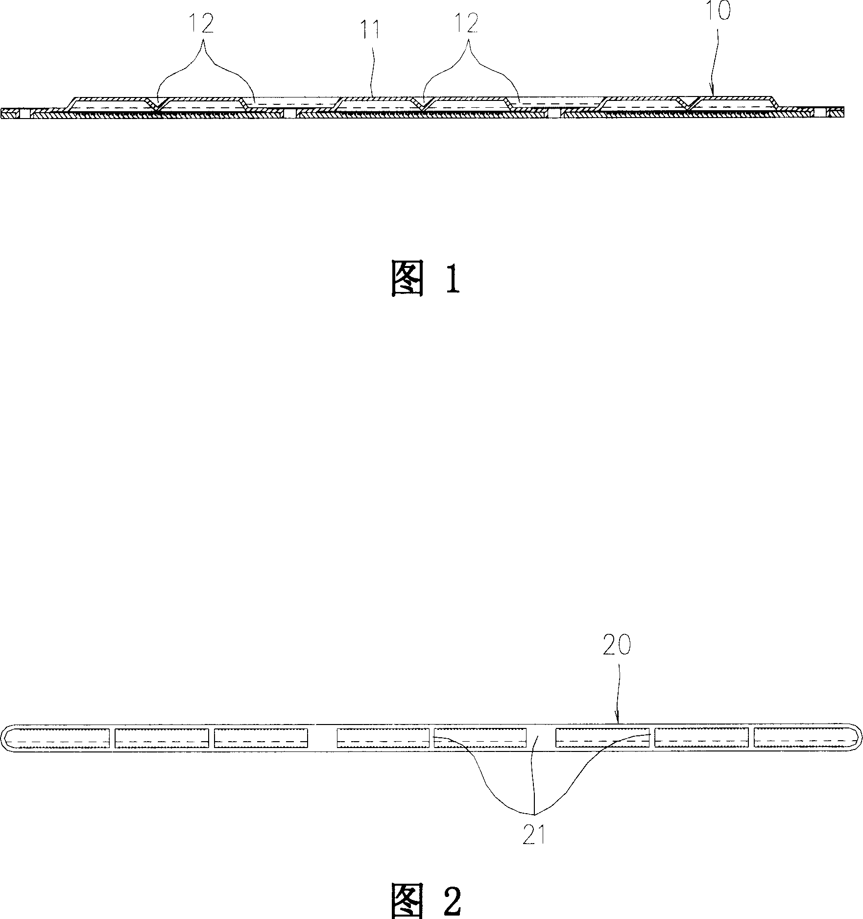
Heat Pipe and Its Manufacturing Method", as shown in Fig. , 12 against each other to achieve the purpose of the support structure, the patent also mentions a
solid straight groove support structure, as shown in Figure 2, a
solid straight groove 21 is formed inside the housing 20 However, the two structures disclosed in the above-mentioned patents all have a common shortcoming, that is, the groove 12 and the
solid straight groove 21 block the fluidity of the steam (vapor-phase
working fluid), thereby affecting the heat dissipation efficiency
[0005] Another example is China's utility model
patent application No. 93220197 "improvement of uniform temperature heat conduction structure", utility model
patent application No. 93205027 "
heat pipe", utility model
patent application No. Application No. 86115415 "
Heat Pipe Radiator", Utility Model
Patent Application No. 88210055 "
Heat Pipe Vapor" and other patents all propose a solid straight groove support structure similar to that shown in Figure 2, so The common
disadvantage is that the solid straight groove support structure blocks the flow of steam (vapor-phase
working fluid), thus affecting the heat dissipation efficiency
[0006] Another example is China's utility model patent application No. 87222042 "circular
heat pipe flattened into flat
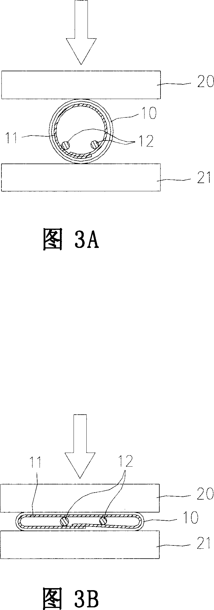
heat pipe structure (1)", which proposes a section that can be a solid circle or a solid circle with grooves or a hollow circle, square or A square support structure with grooves, reticular capillary tissue or sintered capillary tissue is used to support and provide liquid capillary flow. Referring to Fig. The molds 20, 21 sandwich the
pipe body 10 up and down to form a flat heat
pipe structure. A serious
disadvantage of this structure is that the support body 12 is attached to the capillary tissue 11 at a
single point. As shown in the figure, the support body 12 There is no connection between the top of the top and the capillary tissue 11, so that the support body 12 only has a supporting function, and when it is placed in a high temperature environment (such as: an environment greater than 100° such as an oven or reflow
welding), it is impossible to avoid the tube body 10 Expansion and deformation, in other words, since the top of the
pipe body 10 does not have any containment structure, it is very easy to cause the top expansion and deformation
[0007] Another example is the Chinese Utility Model
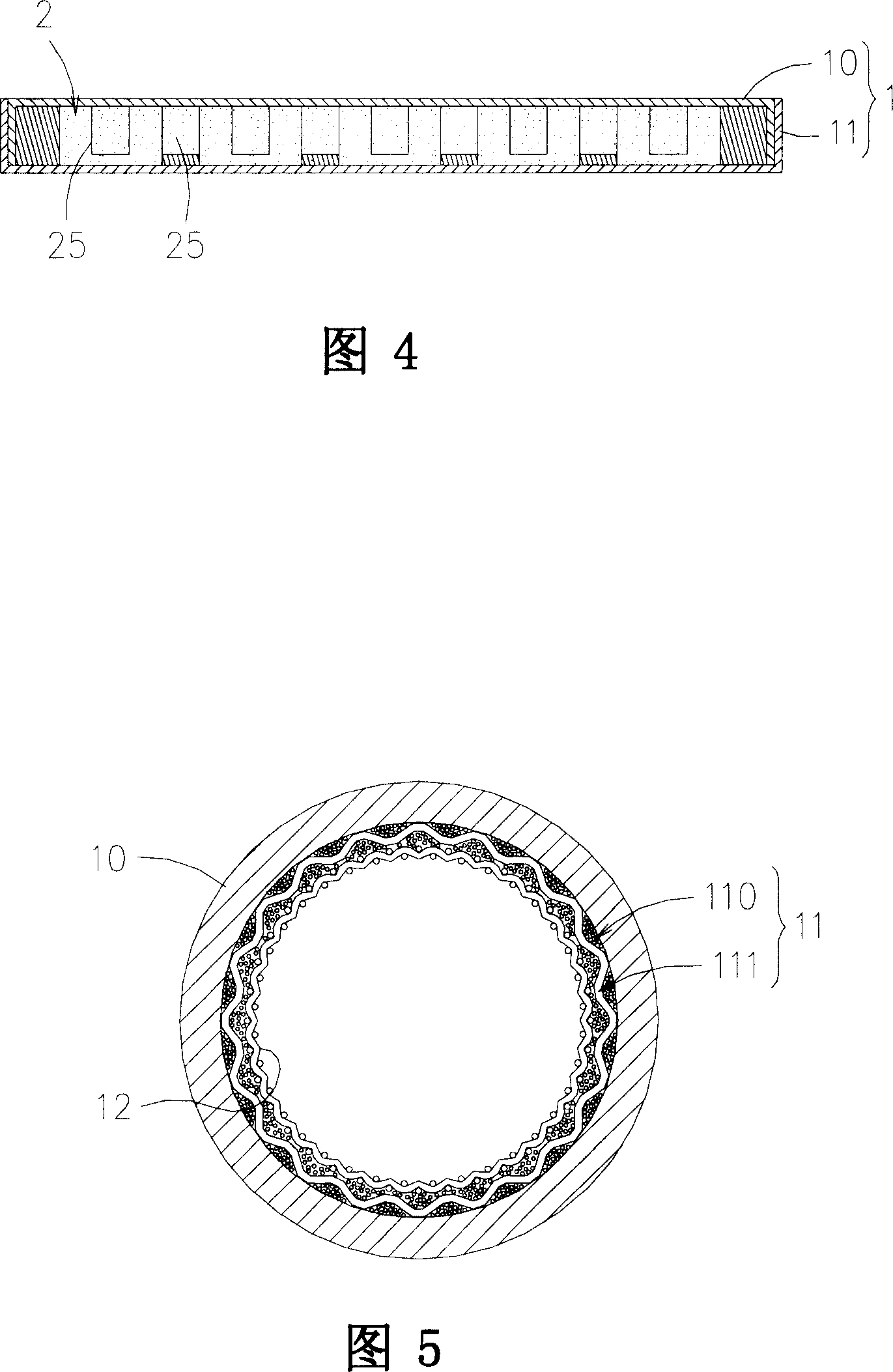
Patent Application No. 92217637 "Supporting Structure Improvement for Flat Heat Pipes". With reference to Fig. 4, the capillary structure and supporting structure 2 are made by
metal powder sintering, and there is a channel 25 between it and the wall surface of the housing 1. It is used for the flow of working steam, and is engaged and fixed with the upper cover 10 and the lower cover 11 of the housing 1 in a sintered manner. Although the support structure 2 has a porous structure, it can provide the capillary conduction capacity of the liquid-phase working fluid, and The
sintering and
welding connection method of its upper and lower large contact surfaces can ensure its structural strength and deformation, so that the shortcomings of the above-mentioned known patents such as the impediment of steam (vapor-phase working fluid) and unfavorable expansion and deformation can be improved, but it still has some problems. Disadvantages: The support structure 2 made of
metal powder sintering makes the flat heat pipe not flexible
[0009] In summary, traditional support structures can be broadly divided into three types: shell joint type, solid plate or columnar structure, and capillary structure. However, no matter what form, they cannot fully satisfy: it has a supporting effect and does not hinder the flow of working fluid. , can prevent expansion and deformation, has the advantages of flexibility, etc.

