Electronic clock

a technology of electronic clocks and clocks, applied in the direction of generating/distributing signals, dynamo-electric converter control, horology, etc., can solve the problems of increasing current consumption unnecessarily, and affecting the operation of the clock. , to achieve the effect of improving the flexibility of second hands available, accurate determination of rotation, and advantageous design techniqu

Active Publication Date: 2012-01-10
CITIZEN WATCH CO LTD
View PDF14 Cites 5 Cited by
  • Summary
  • Abstract
  • Description
  • Claims
  • Application Information

AI Technical Summary

Benefits of technology

[0025]An object of the present invention is to provide an electronic clock that is capable of eliminating the above-mentioned disadvantages and coping with a second hand having a larger moment of inertia than usual, and that has rotation detecting means applicable even to a case where a driving force of a step motor drops.

Problems solved by technology

However, in the conventional technique, detection may not be performed well in some cases where current waveforms are disturbed because a pointer having a large moment of inertia is used for a second hand or the like.
In other words, a phenomenon occurs that although the rotation has been successfully achieved, the correction drive pulse FP is outputted by the erroneous determination, thus increasing current consumption unnecessarily.
Therefore, frequent outputs of the correction drive pulse FP due to the erroneous detection leads to a problem that the battery life decreases significantly.
However, the countermeasure cannot be employed because another problem occurs as described below.
Then, the second detection mode determination circuit 413 erroneously determines that rotation has been successfully achieved, although the rotation has been actually failed.
As described above, if a period of the second detection mode is simply extended, a problem crucial for an electronic clock may occur that a step motor stops to cause a time delay.

Method used


Image

  • Electronic clock
  • Electronic clock
  • Electronic clock

Examples


first embodiment

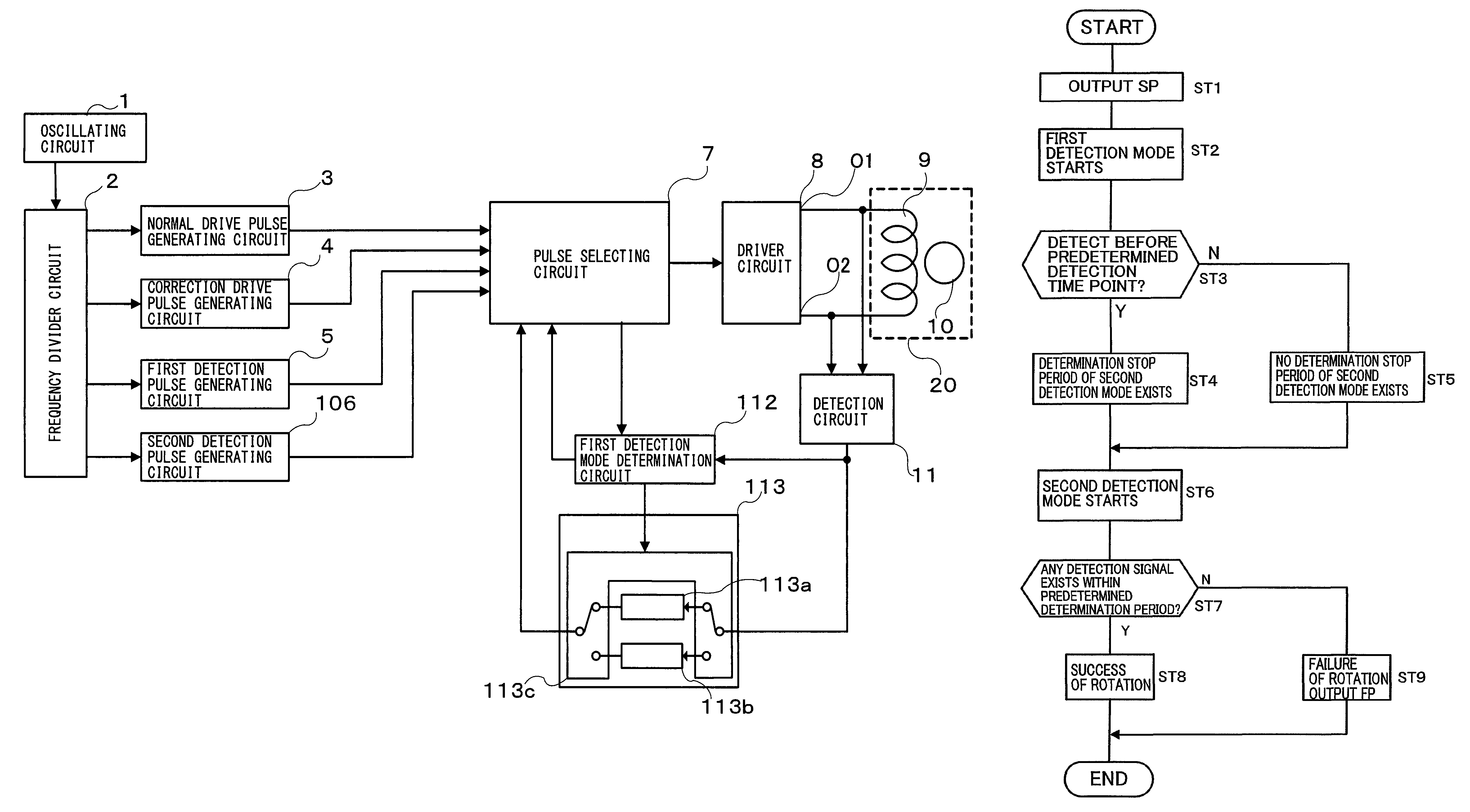
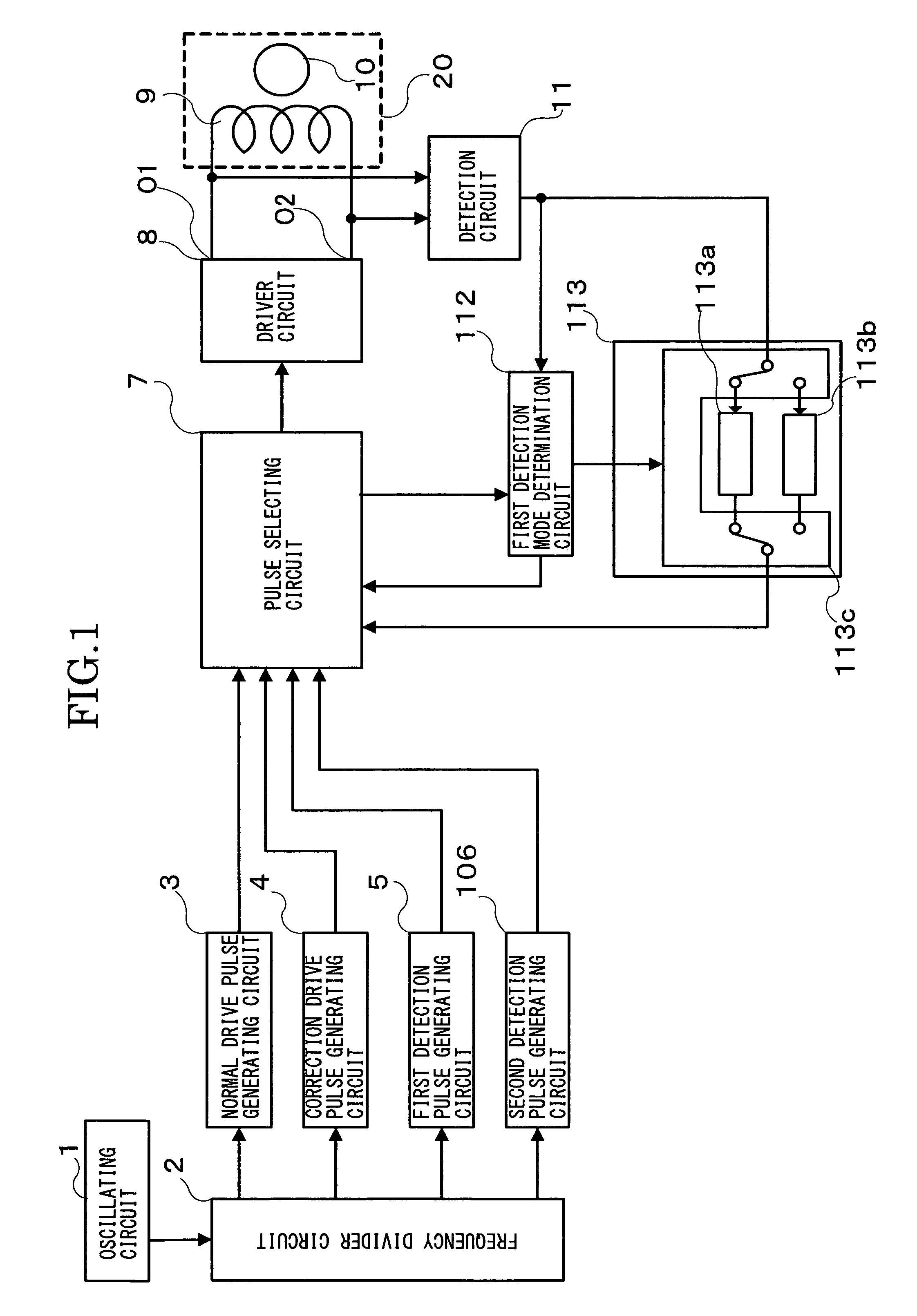
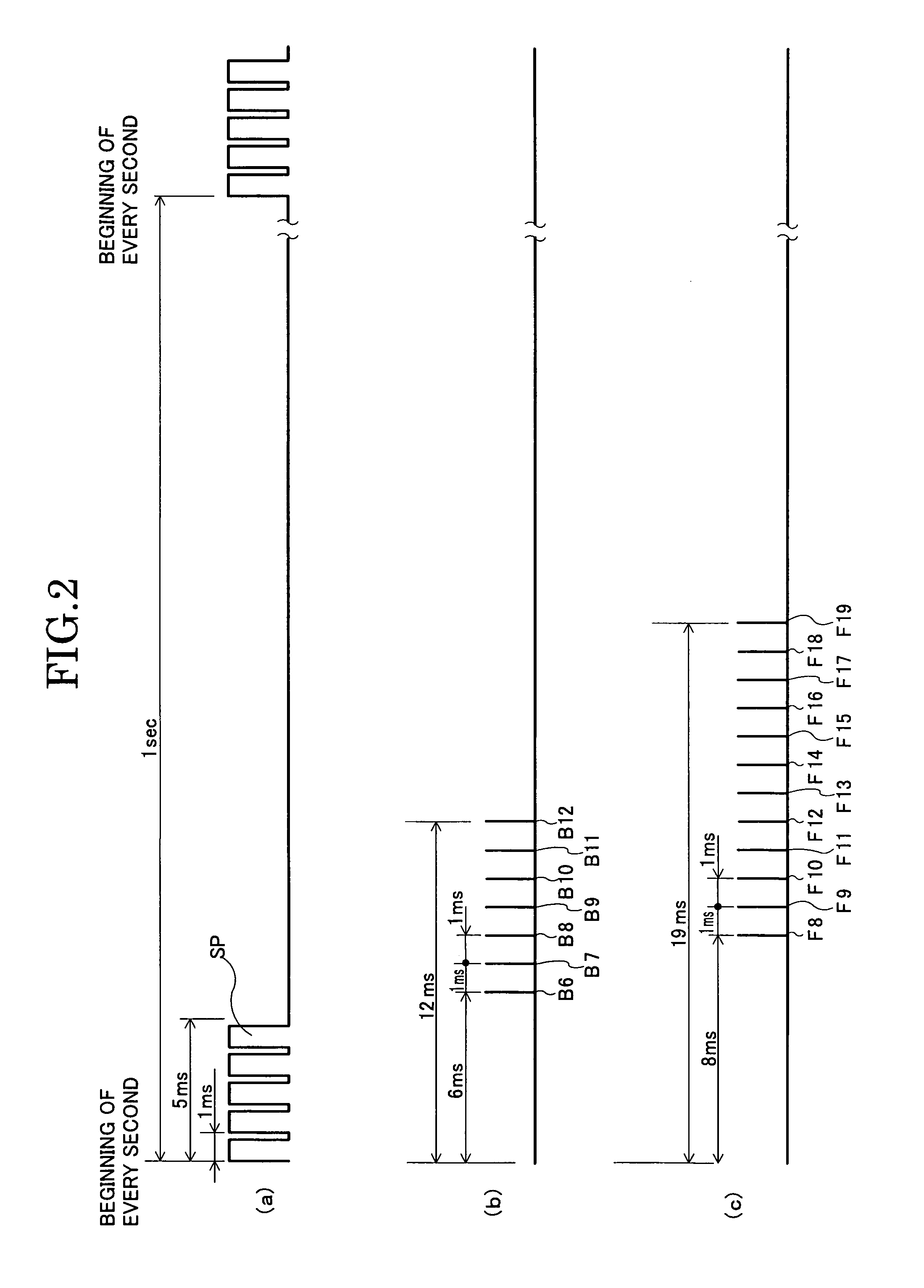
[0086]Hereinafter, a first embodiment of the present invention will be described in detail based on the drawings. The first embodiment is an example of changing the maximum number of detection trials for a detection signal in the second detection mode, based on a determination time for determining the presence or absence of a detection signal in the first detection mode, thereby changing a determination period of the detection signal. FIG. 1 is a block diagram showing a circuit configuration of the electronic clock of the first embodiment. FIG. 2 is a waveform diagram of pulses generated by the circuit of an electronic clock of the first embodiment. FIG. 3 is a diagram of current waveforms and voltage waveforms generated in a coil when a pointer having a large moment of inertia is attached to the electronic clock of the first embodiment. FIG. 4 shows one example of diagrams of current waveforms and voltage waveforms when a rotor of the electronic clock of the first embodiment fails ...

second embodiment

[0106]Next, a second embodiment of the present invention will be described in detail based on the drawings. The second embodiment is an example in which a cycle of detection pulses in the second detection mode is changed in accordance with determination time to determine the presence or absence of a detection signal in the first detection mode, and thereby a determination period of the detection signal is changed. FIG. 8 is a block diagram showing a circuit configuration of an electronic clock of the second embodiment. FIG. 9 is a waveform diagram of pulses generated by the circuit of the electronic clock of the second embodiment. FIG. 3 is a diagram of current waveforms and voltage waveforms (the same drawings as those of the first embodiment) generated in the coil when a pointer having a large moment of inertia is attached to the electronic clock of the second embodiment. FIG. 10 shows one example of diagrams of current waveforms and voltage waveforms generated in the coil when th...

third embodiment

[0122]Next, a third embodiment of the present invention will be described in detail based on the drawings. The third embodiment is an example of changing a cycle of detection pulses on some of the detection signals in the second detection mode in accordance with detection conditions in the first detection mode. FIG. 12 is a block diagram of a circuit configuration of the electronic clock of the third embodiment. FIG. 13 is a waveform diagram of pulses outputted by the circuit of the electronic clock of the third embodiment. FIG. 3 is a diagram of current waveforms and voltage waveforms (the same drawings as those of the first embodiment) generated in the coil when the pointer having the large moment of inertia is attached to the electronic clock of the third embodiment. FIG. 14 is a diagram of current waveforms and voltage waveforms when the rotor of the electronic clock of the third embodiment fails to rotate. Components that are the same as those described in the conventional exam...


PUM


Abstract

An electronic clock makes no erroneous determination of rotation detection and suppresses unnecessary current consumption even when being provided with a second hand having a large moment of inertia. The electronic clock uses a first detection mode determination circuit and a second detection mode determination circuit to perform the rotation detection. The electronic clock includes a determination selecting circuit as changing means for changing the determination period of the second detection mode in accordance with the determination period of the first detection mode. Even when the current waveform is disturbed, erroneous determinations are prevented in a way that the determination terminal of the second detection mode is shortened if the first detection mode terminates earlier. The determination period is changed by the determination selecting circuit selecting either one of a seven-time detection / determination circuit that terminates the determination after seven detection pulses or a six-time detection / determination circuit that terminates the determination after six detection pulses. Alternatively, instead of the number of detection pulses, a cycle of the detection pulses may be shortened.

Description

TECHNICAL FIELD[0001]The present invention relates to an electronic clock having a step motor.PRIORITY CLAIM[0002]This application claims priority from Japanese Patent Application No. 2006-186524, filed on Jul. 6, 2006, the content of which is incorporated herein by reference.BACKGROUND ART[0003]In recent years, an electronic clock has greatly extended battery life by lowering current consumption of a step motor. The lowering of the current consumption of the step motor is achieved by usually driving the step motor with a small driving force that consumes a small amount of current, while driving the step motor with large driving force only when a rotor fails to rotate due to load increase. In a widely-used conventional method of detecting rotation / non-rotation of a rotor, a free vibration pattern of a rotor is determined as follows: after application of a normal drive pulse has terminated, a detection pulse is outputted to quickly change an impedance value of a coil of the step moto...

Claims


Application Information

Patent Timeline
Patent Type & Authority Patents(United States)
IPC IPC(8): G04B19/04
CPCG04C3/143H02P8/38
Inventor SATOH, KOHICHITAKYOH, YUH
Owner CITIZEN WATCH CO LTD
Why Eureka
Try Eureka