Method for determining collision risk for collision avoidance systems

a collision avoidance and collision risk technology, applied in vehicular safety arrangments, process and machine control, electric devices, etc., can solve the problems of high collision risk and decelerating azimuth changes, and achieve the highest collision risk, low collision risk, and high collision risk

Inactive Publication Date: 2012-01-10
THE UNITED STATES OF AMERICA AS REPRESENTED BY THE SECRETARY OF THE NAVY
View PDF8 Cites 48 Cited by
  • Summary
  • Abstract
  • Description
  • Claims
  • Application Information

AI Technical Summary

Benefits of technology

[0005]All objects with collision risk assessment above a predetermined value of P pose no immediate collision risk regardless of azimuth. Among objects having a value of P that indicates a range decrease (indicative of an approach), objects with range change decelerations or with relative changes in azimuth pose a low collision risk. Other objects having an assessed collision risk P above a predetermined value pose a higher collision risk. Objects with constant or accelerating range decreases and constant or decelerating azimuth changes pose the highest collision risk.

Problems solved by technology

Other objects having an assessed collision risk P above a predetermined value pose a higher collision risk.
Objects with constant or accelerating range decreases and constant or decelerating azimuth changes pose the highest collision risk.

Method used


Image

  • Method for determining collision risk for collision avoidance systems
  • Method for determining collision risk for collision avoidance systems
  • Method for determining collision risk for collision avoidance systems

Examples


Embodiment Construction

[0014]The present embodiments herein are not intended to be exhaustive or to limit in any way the scope of the subject matter; rather they are used as examples for the clarification of the subject matter and for enabling others skilled in the art to utilize its teaching. The word “exemplary” is used herein to mean “serving as an example, instance, or illustration.” Any embodiment described herein as “exemplary” is not necessarily to be construed as preferred or advantageous over other embodiments.

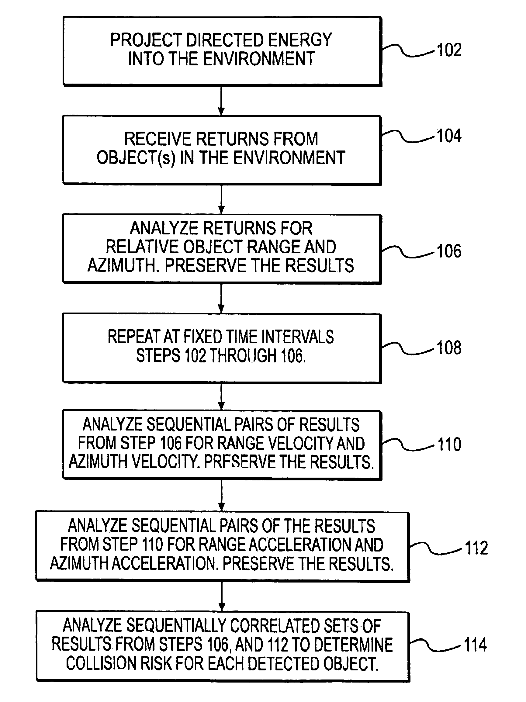
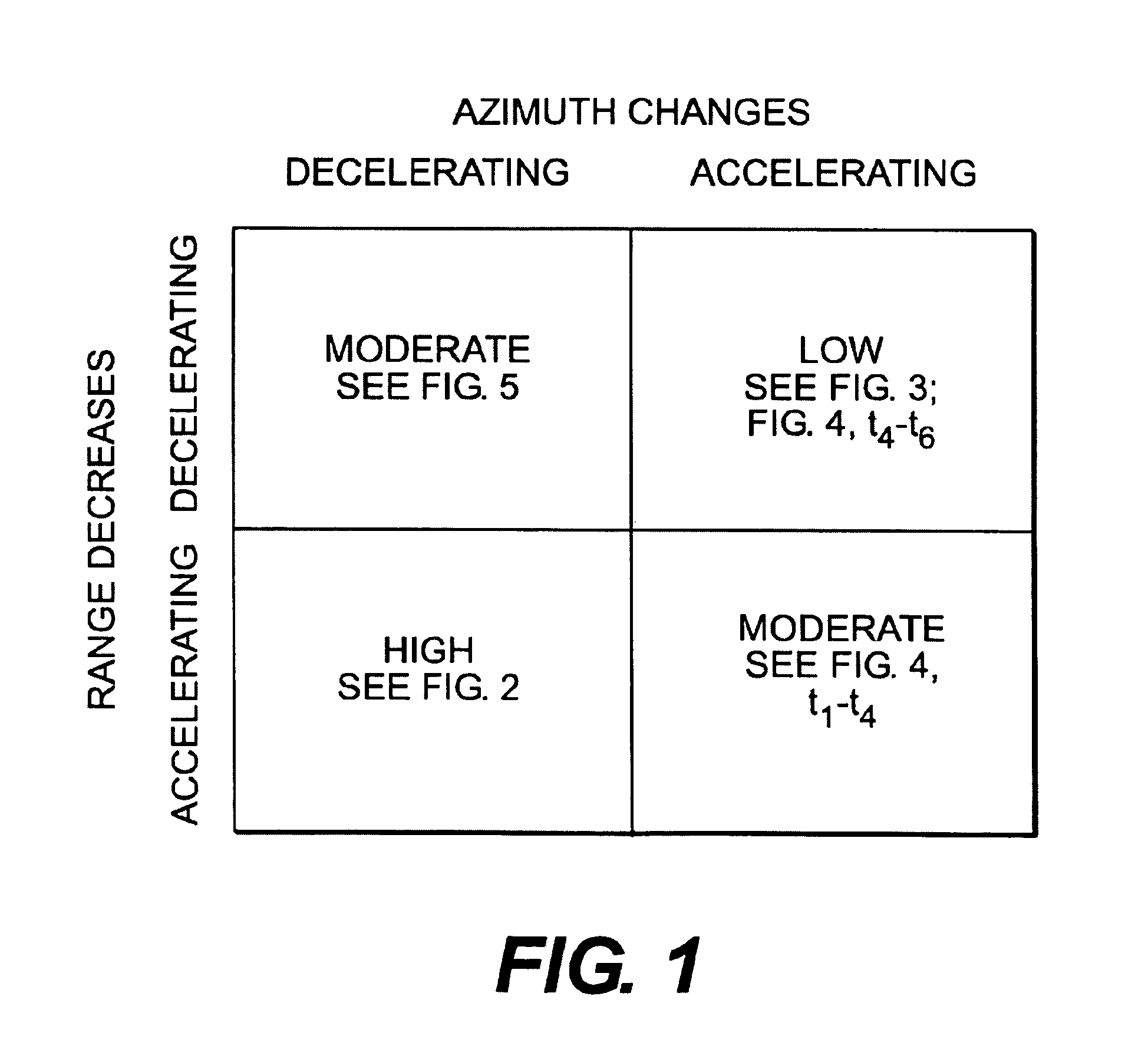
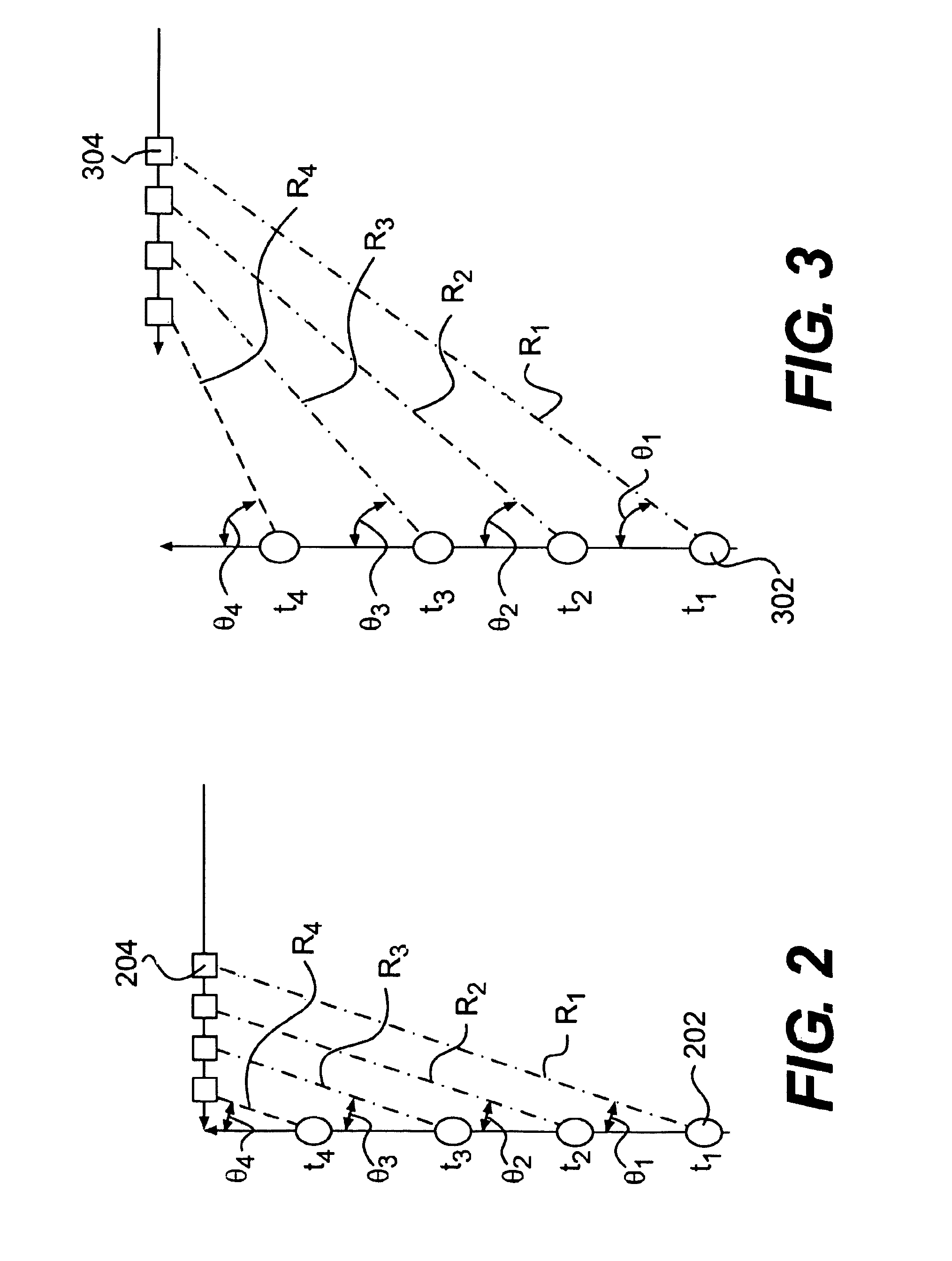
[0015]Because neither range information nor azimuth information alone are adequate to assess collision risk between a moving vehicle and an obstacle, the method of this invention uses the first and second derivatives of the relative range of a detected object with respect to time (relative velocity and acceleration respectively) in combination with change in object azimuth as sensed by the host platform to determine the risk that the object and host will collide. This method involves a shor...


PUM


Abstract

Disclosed is a method and apparatus for determining the risk of an object collision. The method includes transmitting a signal and analyzing a received signal that is indicative of the presence of a remote object. The signal is then analyzed to determine an initial azimuth value and an initial range for the remote object. Subsequent received signals are continuously analyzed to continuously determine subsequent azimuth values, azimuth value velocities and accelerations, as well as subsequent range values, range value velocities and range value accelerations. The factors are then input into a predetermined formula to yield a risk assessment of collision P. The formulas for determining P can be adjusted to account for such factors as number and proximity of remote objects, as well as the speed and maneuverability of both the remote objects and the vehicle that is avoiding collisions with the remote object(s).

Description

FEDERALLY-SPONSORED RESEARCH AND DEVELOPMENT[0001]This project (Navy Case No. 98,408) was developed with funds from the United States Department of the Navy. Licensing inquiries may be directed to Office of Research and Technical Applications, Space and Naval Warfare Systems Center, San Diego, Code 2112, San Diego, Calif., 92152; telephone (619) 553-2778; email: T2@spawar.navy.mil.FIELD OF THE INVENTION[0002]Disclosed is a method for automatically determining the risk of object collisions between a vehicle and a foreign object. The method is intended to work when either the host vehicle or the remote object is moving, or when both the host vehicle and remote object are moving. The method is intended to work with either active or passive target range and direction sensing devices.SUMMARY OF THE INVENTION[0003]A method of determining the risk of an object collision includes the steps of sequentially analyzing the change in range and azimuth (direction) of a remote object with referenc...

Claims


Application Information

Patent Timeline
Patent Type & Authority Patents(United States)
IPC IPC(8): G08G1/16
CPCG08G1/166
Inventor BLACKBURN, MICHAEL R.
Owner THE UNITED STATES OF AMERICA AS REPRESENTED BY THE SECRETARY OF THE NAVY
Why Eureka
Try Eureka