AI technical title is built by Patsnap AI team. It summarizes the technical point description of the patent document.
a battery container and container technology, applied in the direction of cable installation in the cable chamber, cell component details, transportation and packaging, etc., can solve the problem of the most difficult to remove excess dirt, and achieve the effect of reducing the amount of dirt that falls, reducing the amount of excess hydrogen build-up, and simplifying the maintenance procedur
Active Publication Date: 2012-01-17
FOGERLIE SIVERT G
View PDF12 Cites 13 Cited by
Summary
Abstract
Description
Claims
Application Information
AI Technical Summary
This helps you quickly interpret patents by identifying the three key elements:
Problems solved by technology
Method used
Benefits of technology
Benefits of technology
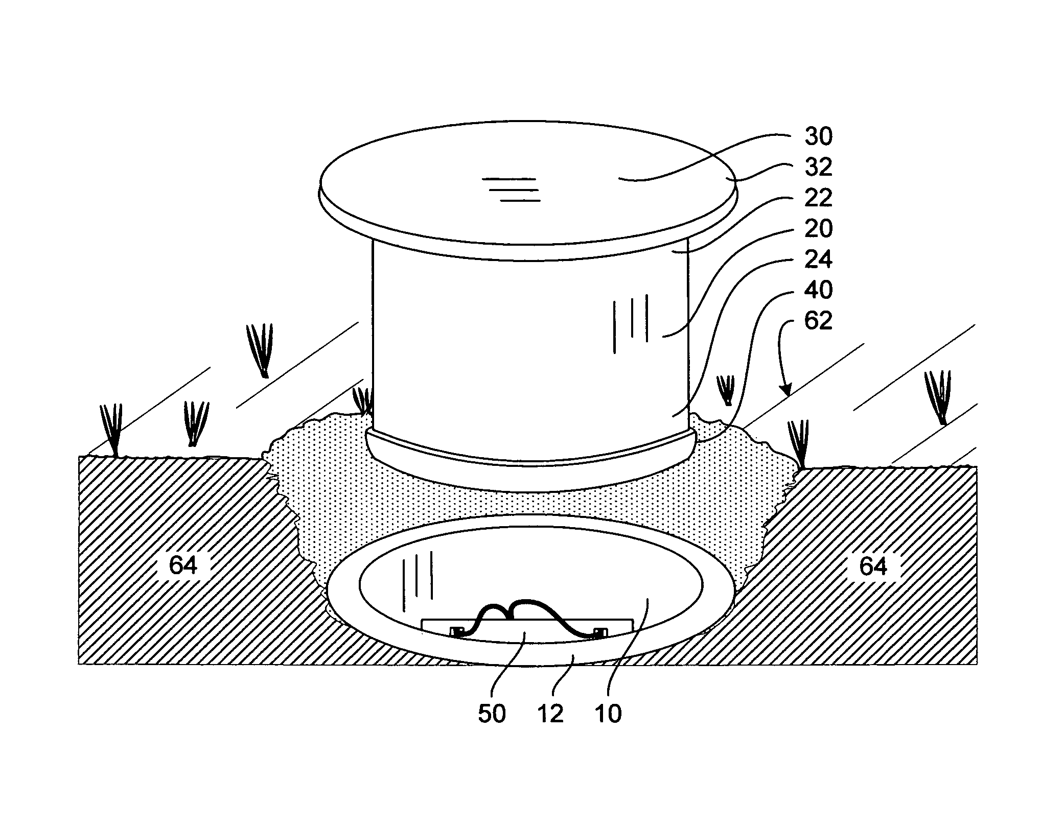
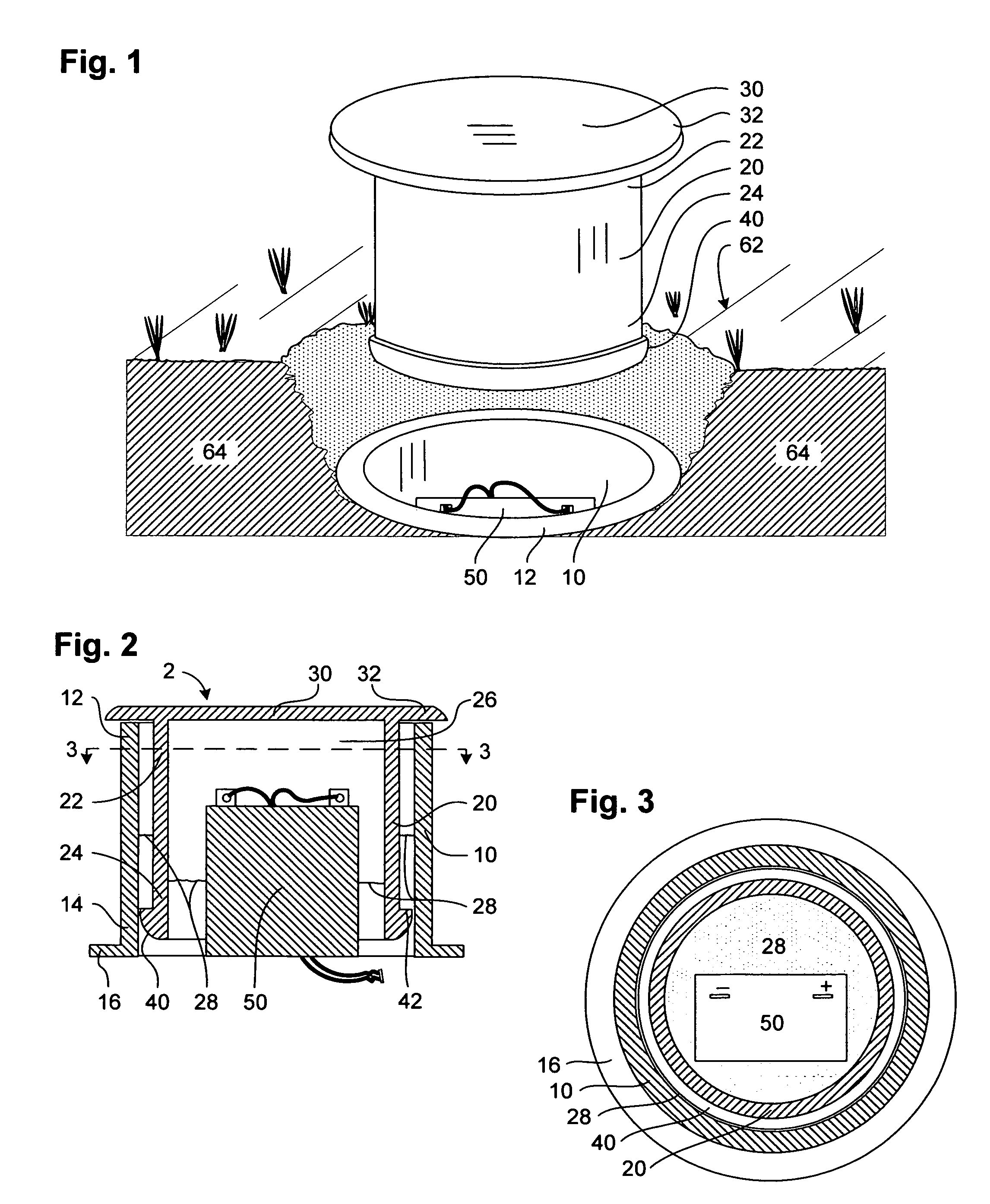
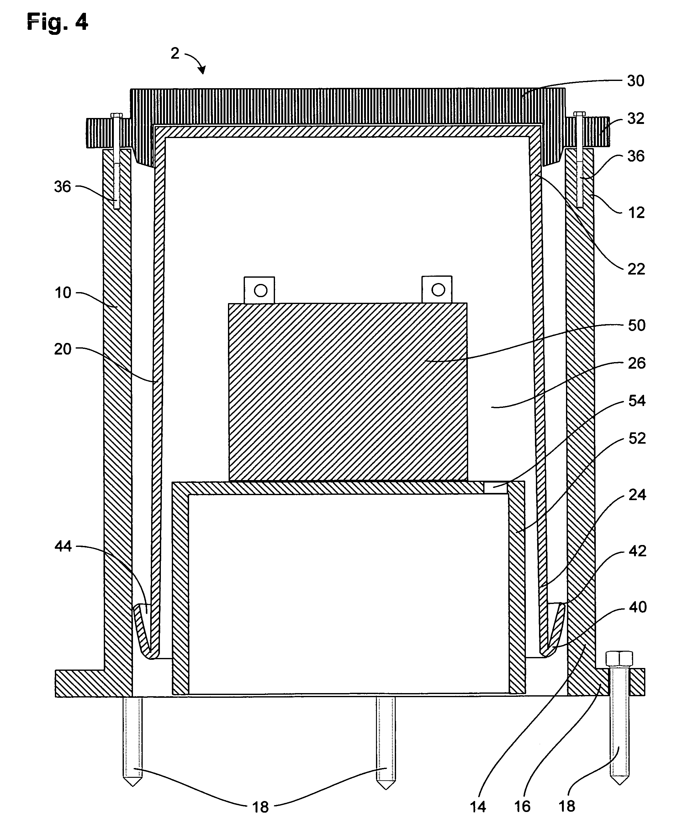
[0003]The present invention is a container system for a battery that is buried underground. The container system comprises an outer enclosure that accepts an inner sleeve. The sleeve includes a cover such that air can become trapped in at least the top portion of the sleeve, similar to a bell jar. In flood conditions, rising water will begin to fill the sleeve from the bottom up, but as the trapped air is pressurized by the rising water, the water level is prevented from rising high enough to contact the terminals of a battery placed inside the sleeve. When the flood conditions subside, the water will be absorbed by the ground. Additionally, because the trapped air is normally in contact with soil at the bottom of the sleeve, there is a gas exchange that can alleviate excess hydrogen build-up from the battery. A battery platform of the preferred embodiment raises the battery higher into the sleeve for added protection.
[0004]An added benefit of the preferred embodiment of the present invention is the use of a ridge positioned around the bottom portion of the sleeve. Excess dirt piled against the bottom of the inside wall of the enclosure can prevent a sleeve from sliding all the way into the enclosure, and this excess dirt is the most difficult to remove because it tends to pack against the enclosure during attempts to remove it by hand. The ridge simplifies a maintenance procedure because accumulated dirt and debris deposited against the inside of the enclosure is scraped away and lifted out of the enclosure every time the sleeve is removed. The scraped outer enclosure is ready to accept the inner sleeve without additional preparation. Furthermore, the ridge is designed to slide over the top of any remaining dirt or debris when the sleeve is inserted into the enclosure, additionally reducing the amount of dirt that falls into the enclosure. With this improved ridge design, one only needs to dig down to the cover of the sleeve in order to access an underground battery kept in the container system. The system is effectively self-cleaning. With the inner sleeve removed, the contents of the container system are very accessible. Once a maintenance action is performed, the inner sleeve is simply dropped back into the outer enclosure and then covered with dirt. Buried power cables are not disturbed during a maintenance action.
Problems solved by technology
Excess dirt piled against the bottom of the inside wall of the enclosure can prevent a sleeve from sliding all the way into the enclosure, and this excess dirt is the most difficult to remove because it tends to pack against the enclosure during attempts to remove it by hand.
Method used
Image
Click on the blue label to locate the original text in one second.
Reading with bidirectional positioning of images and text.
Examples
Embodiment Construction
[0040]This detailed description will begin by describing a battery container system of the present invention that includes an enclosure, a sleeve, a cover and a rechargeable battery. Following will be a description of a bottom portion of the sleeve including the preferred ridge, which is characterized by an edge and a channel for scraping and collecting dirt and debris away form the inside of the enclosure. Finally, there will be a description of how to incorporate battery platforms and electronics into the battery container system.
[0041]The enclosure is a simple structure having closed sturdy walls that are substantially vertical. As seen in FIGS. 1-5, a battery container system 2 preferably has an enclosure 10 that is cylindrical in shape, having a top portion 12 and a bottom portion 14, with a substantially uniform horizontal plane cross-section throughout. The preferred material is any of the various thermoplastic plastics, such as 0.08 inch (2 mm) thick polypropylene or polyvin...
PUM
Abstract
A rechargeable battery, such as a 12 Volt battery that is recharged by a solar panel, is placed into a container system that includes an enclosure, having a top portion that is open and a bottom portion that is open, that is substantially buried underground. A sleeve, having a bottom portion that is open and a top portion that is closed, is lowered into the enclosure such that air is trapped inside the top portion of the sleeve when water collects against the enclosure. The trapped air prevents flood water from rising high enough to contact terminals of the battery. When flood conditions subside, the water drains out the bottom portion of the container system into the ground. Additionally, a ridge around the bottom of the sleeve makes it easier to insert the sleeve into the enclosure because the ridge slides over the dirt and debris, but the ridge scrapes and removes unwanted dirt and debris from the enclosure whenever the sleeve is removed to access the battery. A battery platform may be used to raise a battery higher into the sleeve. The entire container system can be completely buried underground, but access to a battery in the container only requires that the dirt covering the top most part of container be removed, and then the sleeve is simply lifted out of the enclosure without having to dig around the enclosure.
Description
BACKGROUND OF THE INVENTION[0001]Solar panels are increasingly being used to generate power for closed electrical systems, so there is an increased need to protect batteries that store this power. A battery provides a longer life if it is insulated from daily weather changes and protected against theft and vandalism. A commonly suggested way to insulate and protect a 12 volt storage battery is to bury it in the ground. (See U.S. Pat. Nos. 6,422,714, 6,621,181 and 7,075,427.) Although there are some excellent battery vaults available, such as those shown and described in U.S. Pat. Nos. 6,016,828, 6,304,444, 6,356,434, 6,617,973 and 6,772,566, the cost and size of these devices are too large to justify installing one for a simple light. Battery vaults are best suited for large applications, such as back up power for communications systems. For smaller applications, such as supplying power to a pole mounted light in a remote area, most people can only justify purchasing a simple batter...
Claims
Application Information
Patent Timeline
Application Date:The date an application was filed.
Publication Date:The date a patent or application was officially published.
First Publication Date:The earliest publication date of a patent with the same application number.
Issue Date:Publication date of the patent grant document.
PCT Entry Date:The Entry date of PCT National Phase.
Estimated Expiry Date:The statutory expiry date of a patent right according to the Patent Law, and it is the longest term of protection that the patent right can achieve without the termination of the patent right due to other reasons(Term extension factor has been taken into account ).
Invalid Date:Actual expiry date is based on effective date or publication date of legal transaction data of invalid patent.

