Systems and methods for in situ assembly of an interspinous process distraction implant

a technology of in situ assembly and dislocation, which is applied in the field of systems and methods for in situ assembly of an interspinous process dislocation implant, can solve the problems of inability to fully realize the function of the spinal column,

Active Publication Date: 2012-01-17
KYPHON
View PDF124 Cites 19 Cited by
  • Summary
  • Abstract
  • Description
  • Claims
  • Application Information

AI Technical Summary

Problems solved by technology

These degenerative conditions as well as physical trauma can lead to failure or instability of the spinal column.
Spinal stenosis in the neck results in a reduction foraminal area (i.e., the available space for the passage of nerves and blood vessels) which compresses the cervical nerve roots and causes radicular pain.
Another symptom of spinal stenosis is myelopathy, which results in neck pain and muscle weakness.
Extension and ipsilateral rotation of the neck further reduces the foraminal area and contributes to pain, nerve root compression and neural injury.
Open surgery also carries increased risk of infection and other complications.
However, many implants for minimally-invasive spinal interventions must be assembled prior to insertion, thus requiring larger incisions for insertion.
Also, once assembled, the size of the implant cannot be changed inside the patient.

Method used


Image

  • Systems and methods for in situ assembly of an interspinous process distraction implant
  • Systems and methods for in situ assembly of an interspinous process distraction implant
  • Systems and methods for in situ assembly of an interspinous process distraction implant

Examples


Embodiment Construction

[0037]In view of the foregoing background of the invention, it is an object of this invention to provide a spinal implant which may be assembled in situ inside the patient.

[0038]It is also an object of this invention to provide a spinal implant system wherein the size of the implant may be adjusted during the procedure depending on patient anatomy without removal of the implant.

[0039]It is still further an object of this invention to provide a minimally-invasive surgery procedure for installing an implant which may be assembled in situ inside a patient.

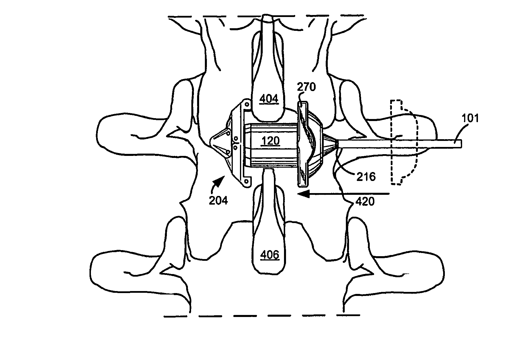
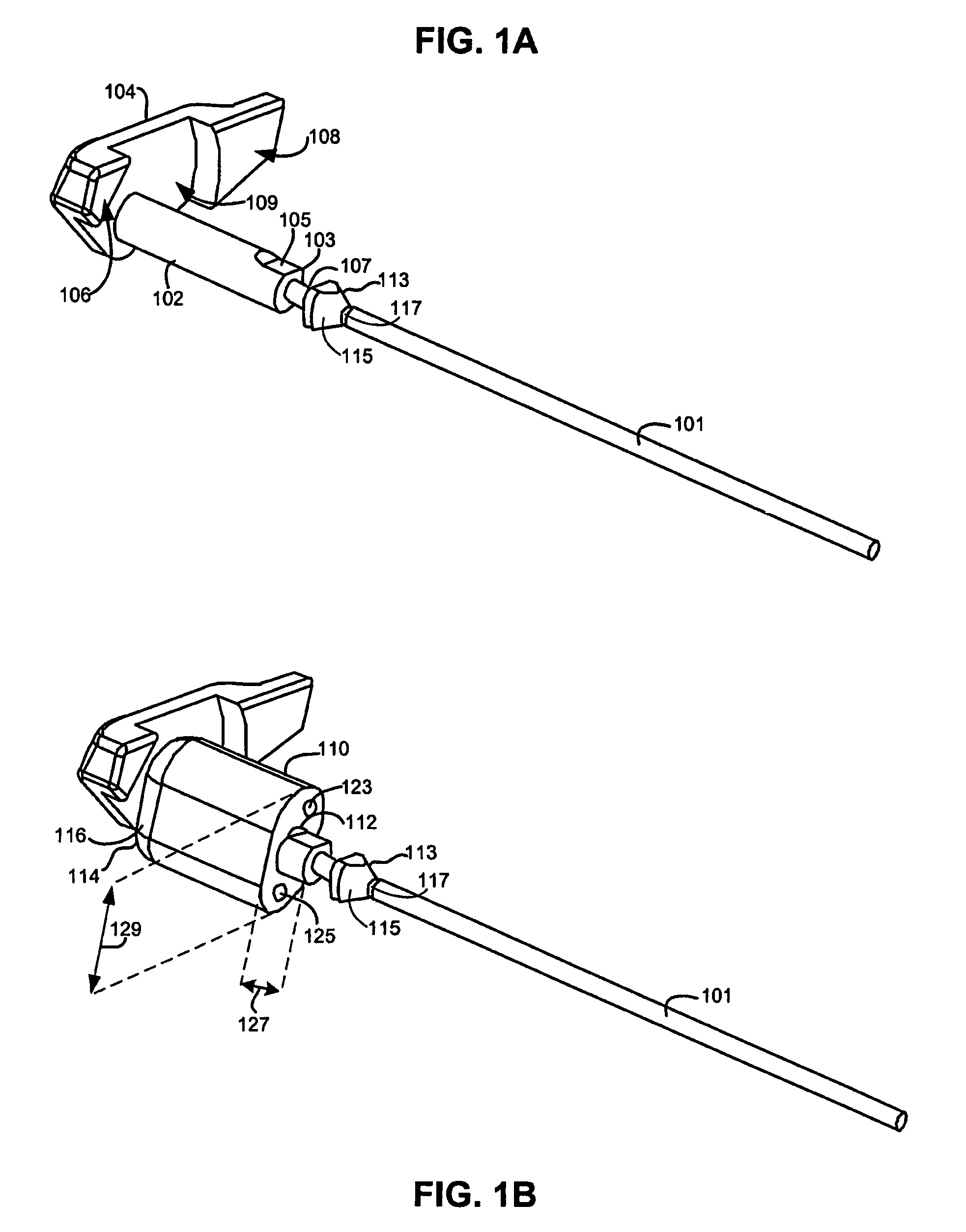
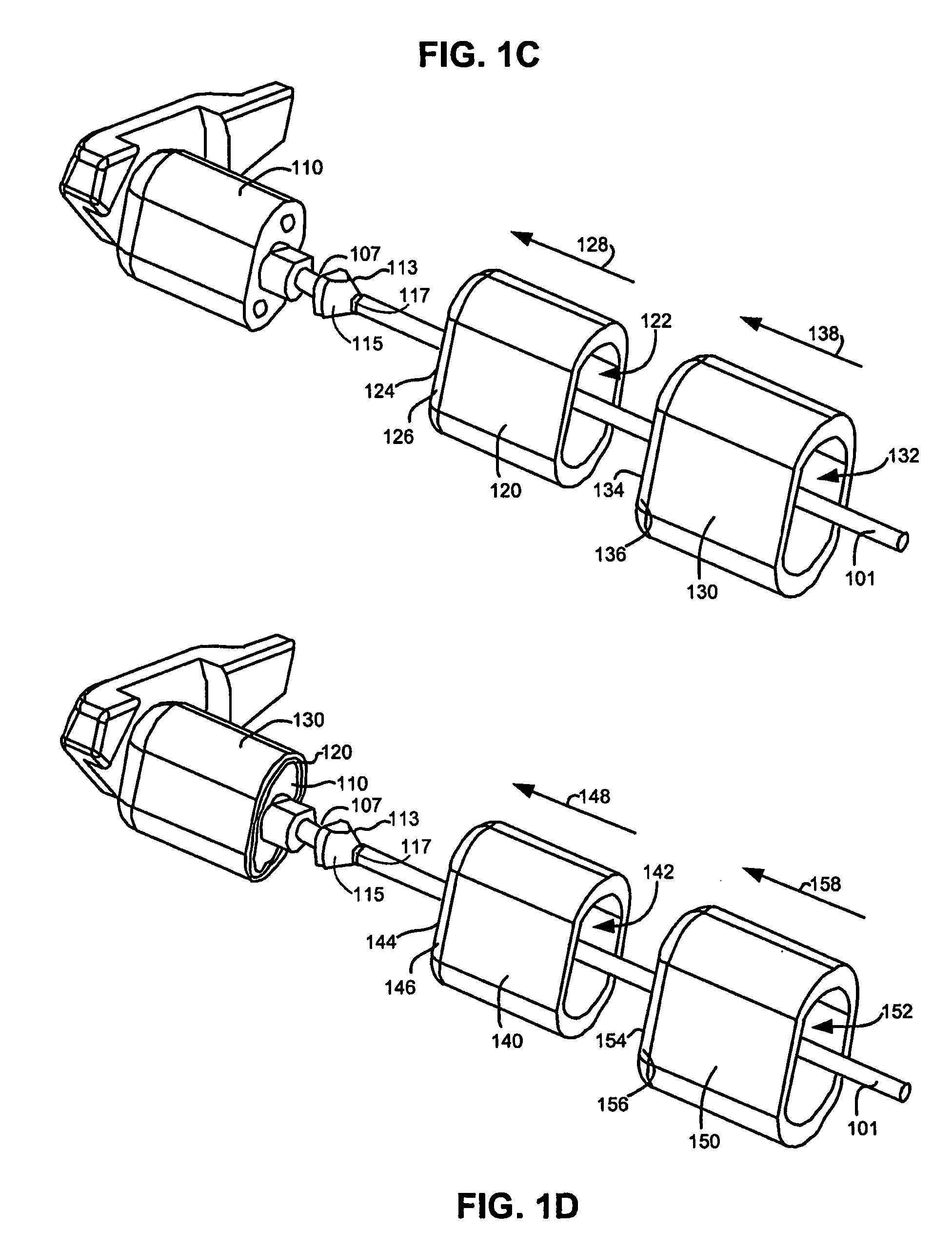
[0040]In accordance with the objects and background of the invention, in one embodiment, the present invention provides an implant system for implantation between adjacent spinous processes for the relief of pain associated with the spine. The implant has a series of spacers which may be inserted over a shaft located between adjacent spinous processes thus allowing the implant to be assembled in situ. The spacers limit extension motio...


PUM


Abstract

An implant system for implantation between adjacent spinous processes for the relief of pain associated with the spine. The implant has a series of spacers which may be inserted over a shaft located between adjacent spinous processes thus allowing the implant to be assembled in situ. The spacers may rotate on the shaft relative to the wings. To minimize trauma to the patient, each spacer has a tapered tissue expander to distract the opening between the spinous processes during assembly. The shaft is connected to a wing, and a second wing or deployable wing may be inserted over the shaft and locked into place.

Description

CROSS-REFERENCES TO RELATED APPLICATIONS[0001]This U.S. patent application claims the benefit of under 35 U.S.C. §109(e) of U.S. Provisional Patent Application No. 60 / 853,963, as filed on Oct. 24, 2006, the disclosure of which is incorporated by reference.STATEMENT AS TO RIGHTS TO INVENTIONS MADE UNDER FEDERALLY SPONSORED RESEARCH AND DEVELOPMENT[0002]Not ApplicableREFERENCE TO A “SEQUENCE LISTING,” A TABLE, OR A COMPUTER PROGRAM LISTING APPENDIX SUBMITTED ON A COMPACT DISK[0003]Not ApplicableBACKGROUND OF THE INVENTION[0004]The spinal column has many functions including supporting the body, weight transfer, motion, and protection of the spinal cord and the nerve roots The spinal column is a structure composed primarily of bones, ligaments, muscles, and cartilage. The bones of the spinal column are called vertebrae.[0005]As the population ages, it is anticipated that there will be an increase in adverse spinal conditions which are characteristic of weakened bone. Also, with aging co...

Claims


Application Information

Patent Timeline
Patent Type & Authority Patents(United States)
IPC IPC(8): A61F2/44
CPCA61B17/7065A61B17/7068A61B2019/307A61B2090/037
Inventor MITCHELL, STEVEN T.WINSLOW, CHARLES J.YERBY, SCOTT A.
Owner KYPHON
Why Eureka
Try Eureka