
Water harvesting device

a water harvesting device and water storage technology, applied in the direction of sewage draining, rigid containers, liquid fuel feeders, etc., can solve the problems of ineffective water collection or even back-up of water toward the building structure, time-consuming maintenance for users, and insufficiently meeting the rising needs of the public. , to achieve the effect of reducing user maintenance, enhancing protection, and maintaining water collection capacity

Inactive Publication Date: 2012-01-17
MAXTECH CONSUMER PRODS
View PDF12 Cites 23 Cited by
  • Summary
  • Abstract
  • Description
  • Claims
  • Application Information

AI Technical Summary

Benefits of technology

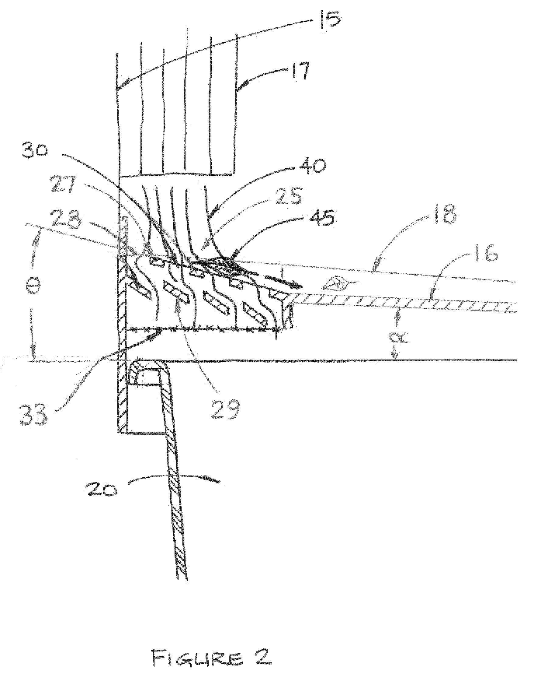
[0009]Thus in the invention, the improved water harvesting device provides the ability to: efficiently collect water while diverting away unwanted debris; do so in all seasons of the year; simplify the installation and maintenance of the device or safeguard the property dwellers and building from harms associated with water collection and storage.
[0022]Yet another object of the invention is to provide a much simpler, quicker, less placement accuracy dependant method of installation for the water harvesting device.

Problems solved by technology

Current devices in the present art are not adequately meeting the rising needs of the public.
In the example of rainwater harvesting from a building collection systems, debris such as twigs, leaves from trees and other matter often accompany rain water exiting from conventional eaves and downspouts and without adequate management of these items water inlet areas can fill and clog with debris resulting in ineffective water collection or even backing up of the water toward the building structure.
There are prior art devices for rainwater collection, filters and the like for installation within the eaves and downspouts but failing to install these or properly maintaining them raises the needs to have these safeguards directly integrated with the water harvesting device.
Furthermore, many prior art devices that capture such debris requires frequent and regular maintenance is required to keep the inlet are clean resulting in time consuming maintenance for the user.
These debris items, twigs for example are often shaped such that they can also enter the water inlet and potentially cause damage to internal components of a water harvesting device.
In the example of a rainwater harvesting device, filtering devices or mosquito safety screens installed at the inlet are susceptible to damage from entering debris.
Once a tear or hole is pierced in the safety netting mosquitoes are free to enter the device and lay their eggs, potentially leading to the undesired breeding of the West Nile Virus.
Current rainwater harvesting devices do not facilitate management of this debris as such.

Method used


Image

  • Water harvesting device
  • Water harvesting device
  • Water harvesting device

Examples


Embodiment Construction

[0030]Turning now descriptively to the drawings, in which a preferred embodiment is shown in the various configurations to describe the invention. It will be understood that while the invention is described with respect to a preferred embodiment the device may be configured differently while achieving the essence of the invention.

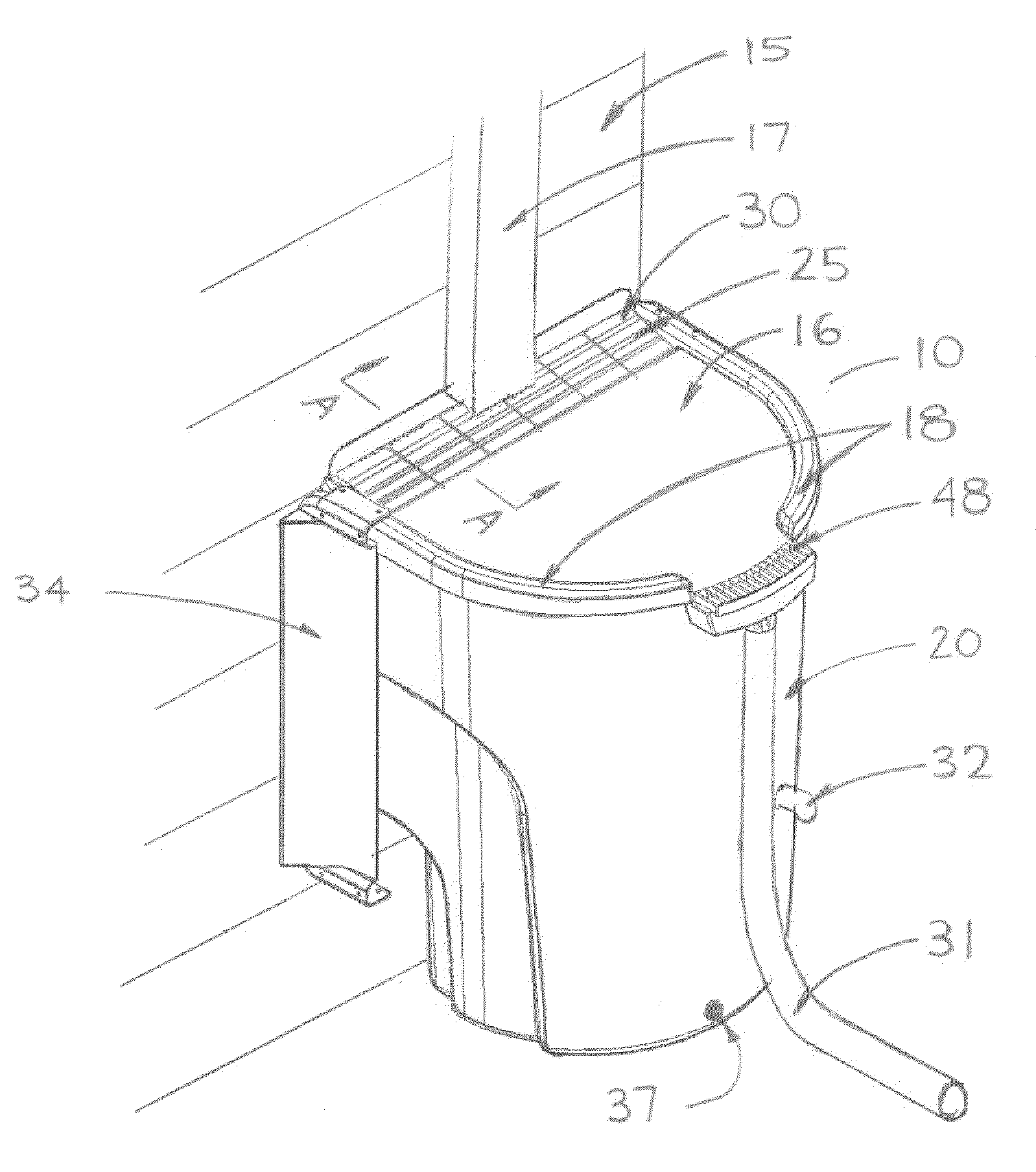
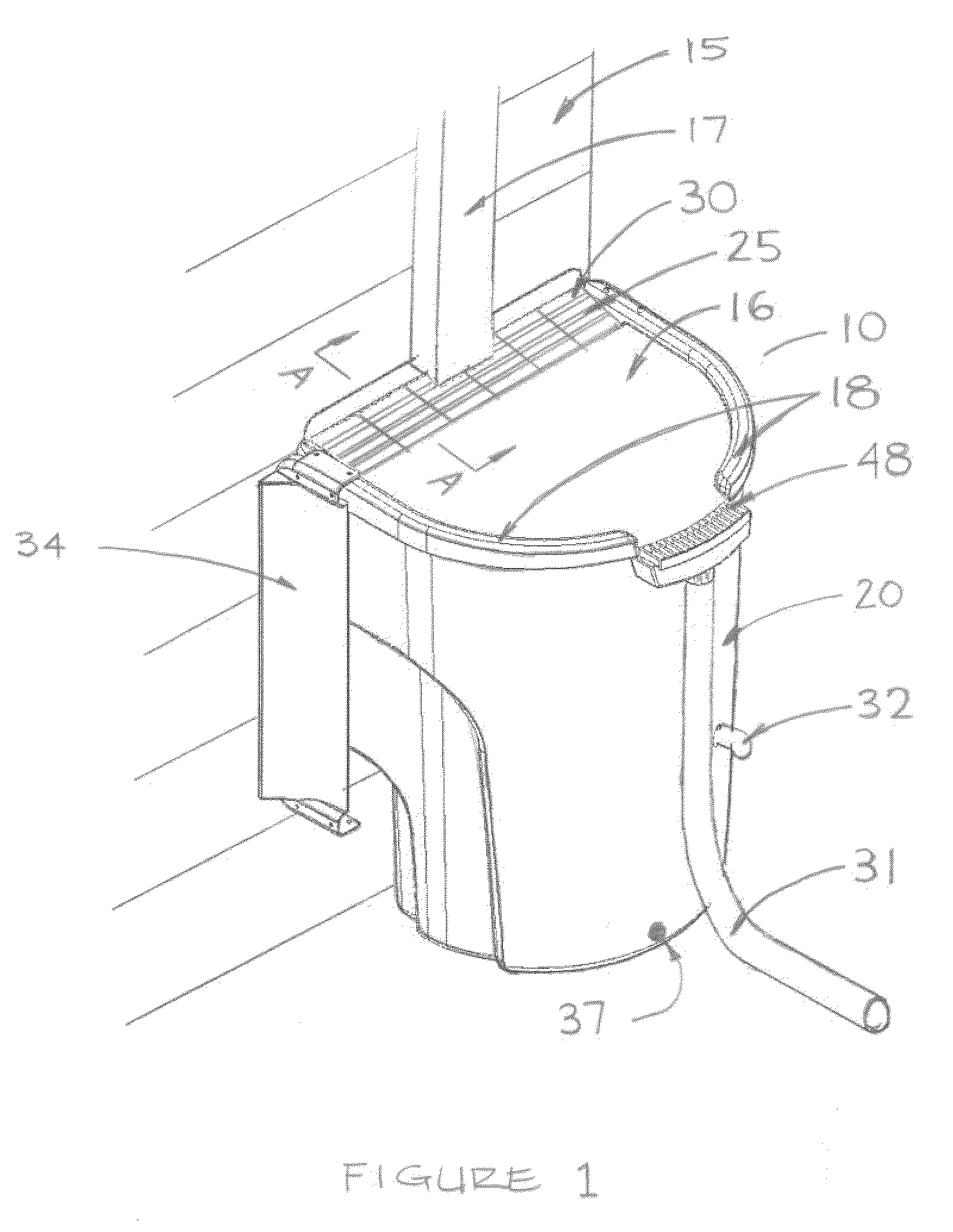
[0031]FIG. 1 illustrates a preferred embodiment, a rain water harvesting device 10 in an installed position. The rainwater harvesting device 10 is shown adjacent to a wall 15 of a residential building. The wall 15 is shown with a downspout 17 attached to it and represents one typical configuration prepared for use with a rainwater harvest device. Rainwater that is collected from building structures are collected using eaves (not shown), the water then enters into the downspout 17. The downspout 17 is positioned above the rainwater harvest device 10 such that the water exiting the downspout 17 spills onto the rainwater harvest device 10. For basic operation ...


PUM

PropertyMeasurementUnit
areaaaaaaaaaaa
water entry areaaaaaaaaaaa
timeaaaaaaaaaa

Abstract

The device disclosed is an improved water harvesting device providing the capability of diverting debris away from a water entry area and reducing potential for clogging of the water entry area. The water harvesting device comprises a tank portion for containment of water and a water entry portion for receiving water, particularly rainwater from a building water collection system such as an eaves and downspout configuration. Debris typically accompanying rainwater as it exits from the downspout of the building collection system is diverted away from the water entry area allowing for better water collection efficiency, preventing backing of water and reducing operator maintenance of the device.

Description

CROSS REFERENCE TO RELATED APPLICATIONS[0001]This application claims the benefit of U.S. Provisional Application No. 61 / 088,367 filed Aug. 13, 2008 and U.S. Provisional Application No. 61 / 096,237 filed Sep. 11, 2008 which is incorporated herein by reference.FIELD OF THE INVENTION[0002]The present invention relates generally to devices for capturing and storing water such as the devices used in harvesting rainwater commonly referred to also as rain barrels. More particularly, the present invention relates to such a device for use above ground, aside the exterior wall of small buildings predominantly used in conjunction with common rainwater collection systems such as those found on residential dwellings and small commercial structures.BACKGROUND OF THE INVENTION[0003]It can be appreciated that water harvesting devices have been around for years. The purpose of these devices is quite simple, that is to capture water and store it for later use. One common example as such is the commonl...

Claims


Application Information

Patent Timeline
Patent Type & Authority Patents(United States)
IPC IPC(8): B01D35/027
CPCE03B3/03E03F1/002C02F2103/001C02F2303/24Y10T137/6969Y02A20/00Y02A20/108
Inventor ALLAN, SCOTT WILLIAM
Owner MAXTECH CONSUMER PRODS
Learn More