Ceiling fan with rotary blade surface light

a technology of rotary blades and ceiling fans, which is applied in the direction of lighting and heating apparatus, liquid fuel engines, heating types, etc., can solve the problems of reducing the life and performance of leds, reducing the efficiency of lighting and heating, and not revealing the cooling of light sources and rotary blades. , to achieve the effect of preventing a temperature increas

Inactive Publication Date: 2012-01-24
NEC LIGHTING
View PDF11 Cites 13 Cited by
  • Summary
  • Abstract
  • Description
  • Claims
  • Application Information

AI Technical Summary

Benefits of technology

[0015]The present invention has an object to provide a ceiling fan with a blade surface light that causes a light source to flash at predetermined intervals to prevent a temperature increase.
[0023]On the other hand, rotation of a light source causes rotation of a shadow of the illuminated object, which causes an uncomfortable feeling, but the rotating light source is lit in a predetermined range on a rotation circumference, and extinguished outside the range, thereby eliminating the uncomfortable feeling.
[0024]In the present invention, the light is provided on the rotary blade surface of the ceiling fan that has a blade surface light, and thus heat generated from a light source is cooled by air brought into contact with the light source by the rotation of the rotary blade, and the light source is caused to flash at regular intervals during rotation to prevent heat generation, and effectively cools the heat generated from the light source.
[0025]The light source is lit only in the predetermined rotation range of the rotary blade, thereby reducing movement of the shadow of the illuminated object, and eliminating the uncomfortable feeling caused by flashing.

Problems solved by technology

Without proper radiation, the life and performance of the LED may be significantly shortened and impaired.
Utility Model Registration No. 3109730 does not disclose cooling of the light source and the rotary blade.
When the capacity of the light source is small, the temperatures of the light and the rotary blade may be kept within a safe range by radiation from a rotary blade surface, but when the light source requires a larger illumination capacity, the amount of heat generated is increased, and the temperatures of the light and the rotary blade may exceed the safe range.
However, in facilitating radiation by such means, a large surface area of a radiator is required for increasing convection to air and radiation efficiency, which increases the size of the light.
When the size or structure of the light is restricted, electric power input to the light source needs to be reduced for a balance with radiation, which may prevent desired brightness from being obtained.
However, these examples are intended for displaying various visual light patterns with a portable fan rather than cooling the light emitting member, and cannot be applied to a ceiling fan having a blade surface light intended for illumination.

Method used


Image

  • Ceiling fan with rotary blade surface light
  • Ceiling fan with rotary blade surface light
  • Ceiling fan with rotary blade surface light

Examples


Embodiment Construction

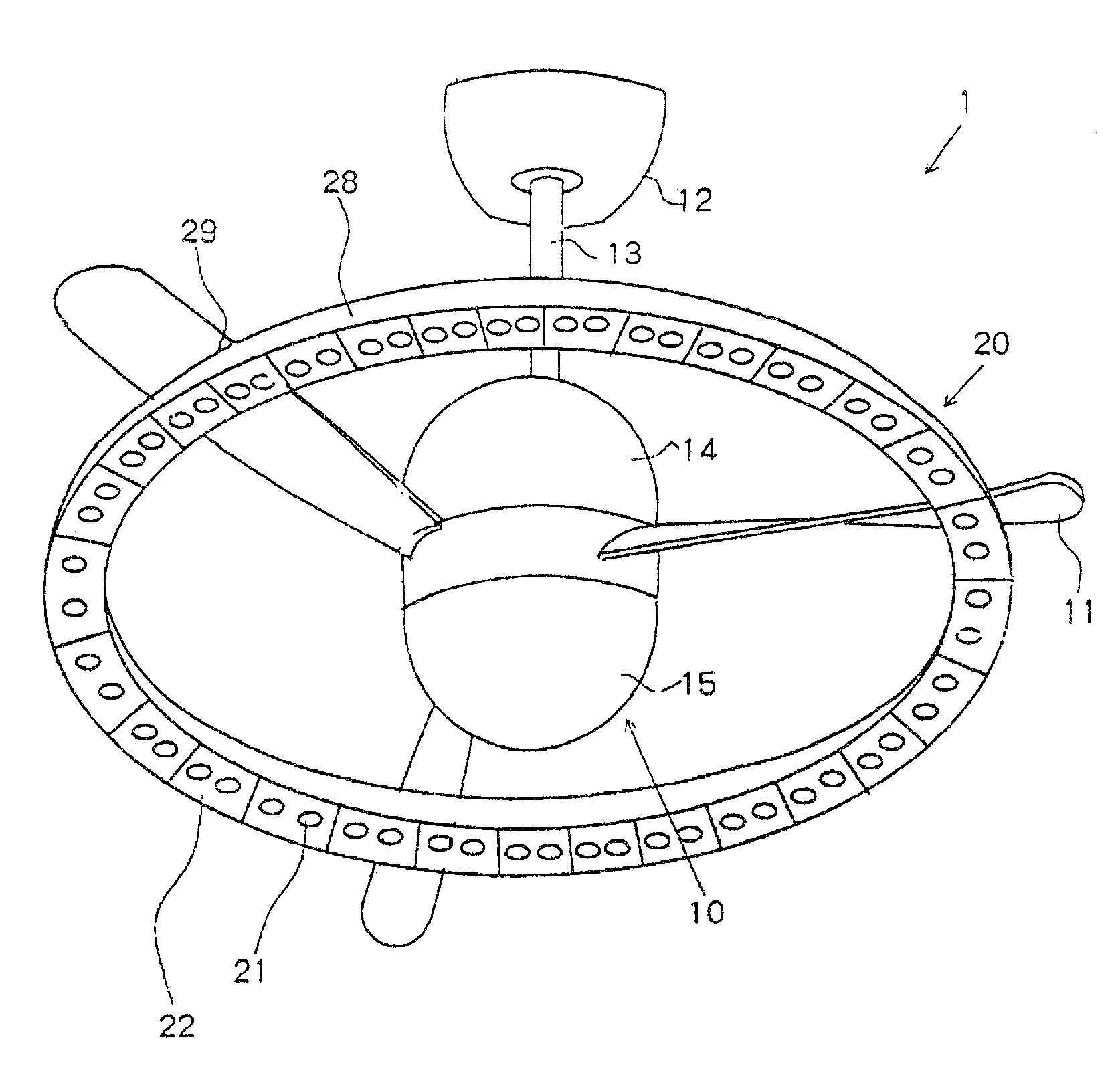
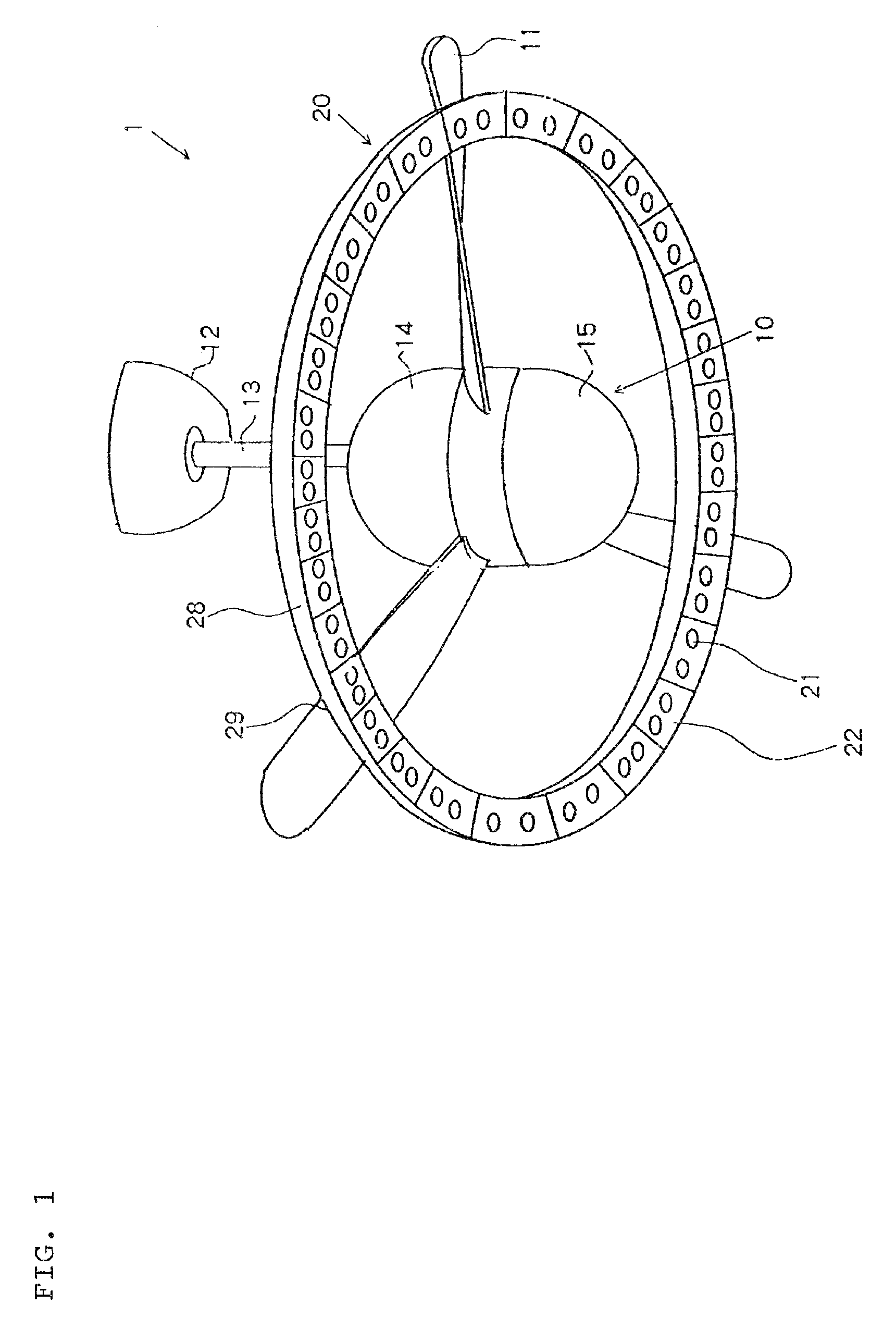
[0038]An exemplary embodiment of the present invention will be described with reference to the drawings. FIG. 1 is a perspective view of a ceiling fan with a blade surface light of an exemplary embodiment of the present invention.

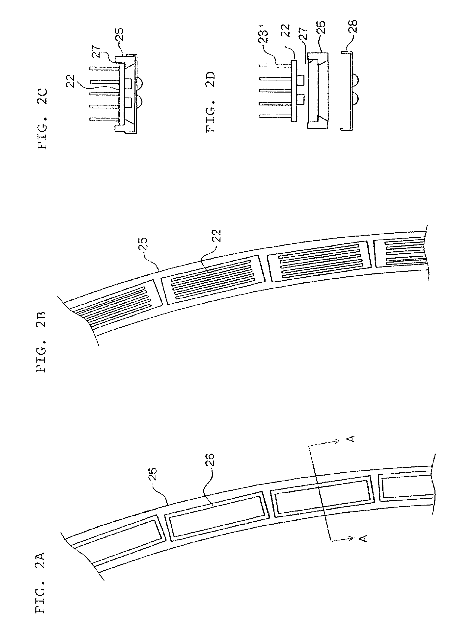
[0039]Ceiling fan having blade surface light 1 of the exemplary embodiment of the present invention includes ceiling fan 10, and annular blade surface light 20 secured at light mounting portions 29 to lower surfaces near the tips of rotary blades 11 of ceiling fan 10. In this case, providing the annular blade surface light 20 closer to the tips of the rotary blades 11 increases a moving speed of LEDs 21 and more effectively facilitates radiation from radiating fins 23 described later. The LEDs are used as light sources, but not limited to this, any light sources that can be continuously placed in the blade surface light housing, for example, small light bulbs may be used.

[0040]Ceiling fan 10 is secured to the ceiling by an mounting tool, not shown, in ceili...


PUM


Abstract

In a ceiling fan having a blade surface light, an annular blade surface light including a plurality of LEDs that are light emitters that are continuously placed is secured on a circumference that connects sides near tips of a plurality of rotary blades of the ceiling fan, and the light emitters are lit by a lighting controller only when they are in a predetermined range on a rotation reference circumference. LED devices housing the LEDs that are the light emitters and that are provided with cooling fins are housed in an annular LED case, and the LED case is secured to the rotary blades. Thus, the LEDs radiate heat from the cooling fins provided in the LED devices by rotation of the rotary blades, and they are intermittently lit and extinguished to prevent a temperature increase. The LEDs only in the predetermined range are lit, thereby preventing any uncomfortable feeling when LEDs are caused to flash.

Description

[0001]This application is based upon and claims the benefit of priority from Japanese patent application No. 2007-027875, filed on Feb. 7, 2007, the disclosure of which is incorporated herein in its entirety by reference.BACKGROUND OF THE INVENTION[0002]1. Field of the Invention[0003]The present invention relates to a ceiling fan with a rotary blade surface light, and more particularly to a ceiling fan with a rotary blade surface light for flashing a light source of a light at a predetermined rotation position on a rotary blade.[0004]2. Description of the Related Art[0005]As means for circulating indoor air for comfortable air-conditioned environments, ceiling fans have been used that include a rotating blade placed near a ceiling and that circulate indoor air by the flow of air caused by rotation of the blade. In recent years, ceiling fans having a light including an integrated illumination light have been also used.[0006]Utility Model Registration No. 3109730 discloses a ceiling f...

Claims


Application Information

Patent Timeline
Patent Type & Authority Patents(United States)
IPC IPC(8): F04D29/00
CPCF04D25/088F04D29/005F21V33/0096F04D25/08F24F13/078
Inventor OKIMURA, KATSUYUKI
Owner NEC LIGHTING
Why Eureka
Try Eureka