Surgical sagittal saw with quick release indexing head and low blade-slap coupling assembly

a sagittal saw and indexing head technology, applied in the field of surgical sagittal saws, can solve the problems of generating a significant amount of noise, affecting the use of power driven reciprocating saws, and current saw blades not tightly fitting into the saw head slots, and achieves the effect of convenient rotation

Active Publication Date: 2012-01-24
STRYKER CORP
View PDF10 Cites 23 Cited by
  • Summary
  • Abstract
  • Description
  • Claims
  • Application Information

AI Technical Summary

Benefits of technology

[0013]Specifically, the surgical sagittal saw of this invention includes a head and a neck subassembly. The neck is rotatably fitted in a static front collar. Ball bearings facilitate rotation of the neck relative to the front collar. A retention assembly holds the head and neck assembly to the front collar. A locking assembly separate from the retention assembly holds the neck in a fixed rotational position relative to the front collar.

Problems solved by technology

While current surgical saws, with tooless heads, have proven to be useful surgical tools, there is a disadvantage associated with their use.
When an oscillating motion saw with this type of head is actuated, it generates a significant amount of noise.
This is because current saw blades do not tightly fit into the saw head slots in which they seat.
Secondly, there is a slight gap due to the inherent manufacturing tolerances that arise during fabrication of these components.
Each time this motion occurs, noise is produced.
The cumulative noise produced by the saw blade repetitively striking the interior walls of the saw head in which it is seated is quite noticeable.
However, it is costly to precision machine the tapered pins used to hold the saw blade in the head.
One disadvantage of known indexing mechanisms is that, for the saw head and neck to be rotated, the surgical personnel must employ a significant amount of manual force to overcome the retention mechanism used to hold the head and neck to the rest of the handpiece.
Still another disadvantage of known indexing assemblies is that, over time, a corrosive bond may form between the fixed collar and the rotating neck.
When such bonding occurs, it becomes increasingly difficult to use manual force to index the saw head and neck relative to the static collar.
This loose fit causes the tab to vibrate against the surface of the adjacent slot-defining surfaces.
This contact adds to the noise produced when the saw is actuated.

Method used


Image

  • Surgical sagittal saw with quick release indexing head and low blade-slap coupling assembly
  • Surgical sagittal saw with quick release indexing head and low blade-slap coupling assembly
  • Surgical sagittal saw with quick release indexing head and low blade-slap coupling assembly

Examples


Embodiment Construction

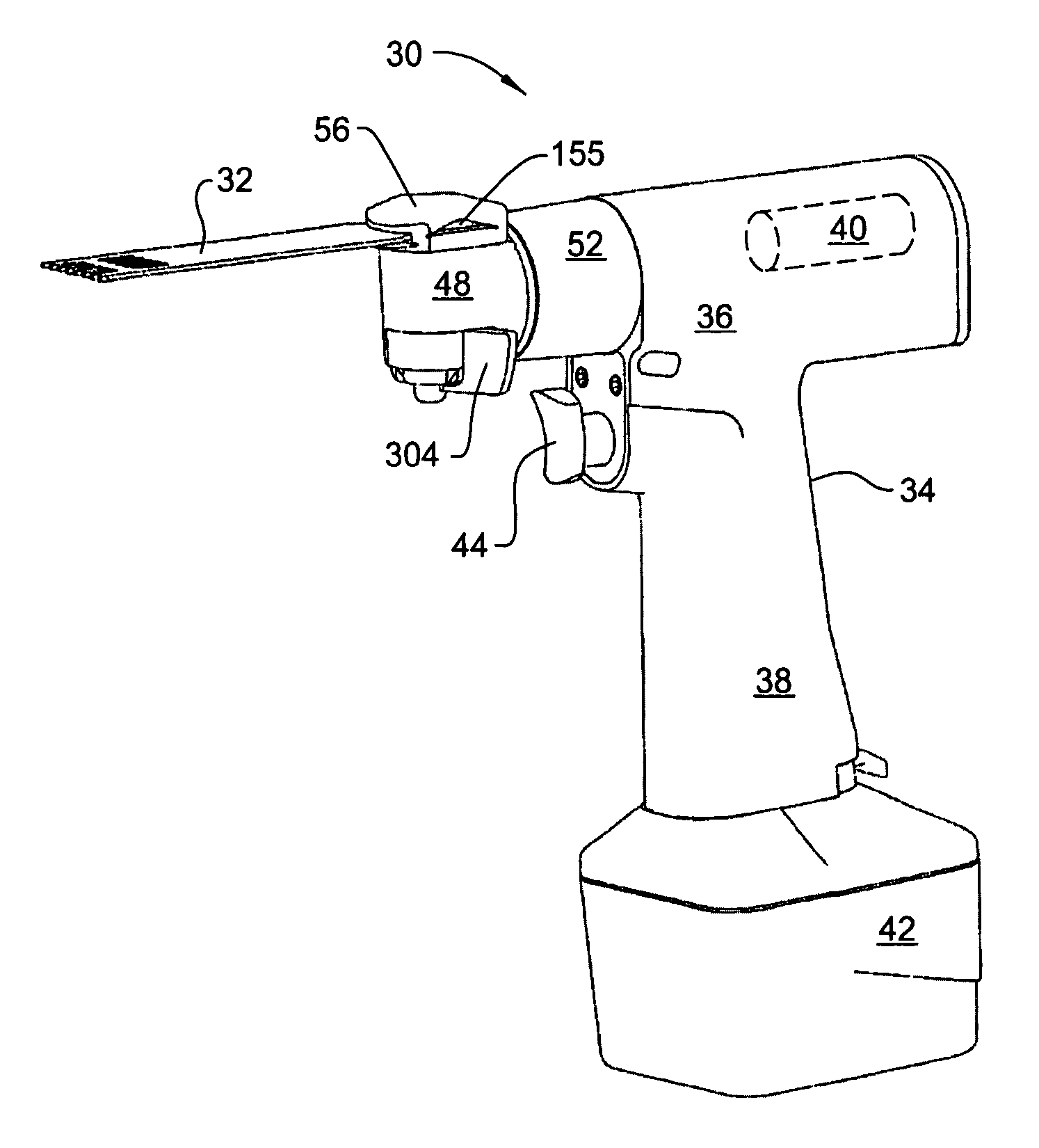
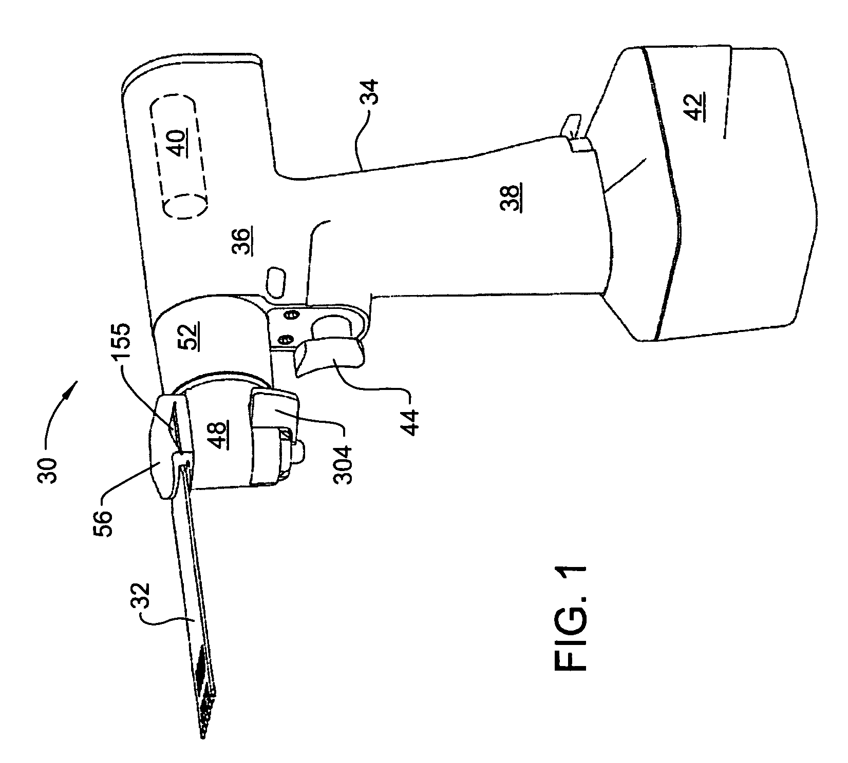
[0044]FIG. 1 illustrates a surgical sagittal saw 30 constructed in accordance with this invention for oscillating a saw blade 32. Saw 30 includes a housing 34. In the particular version of the invention, housing 34 is shaped to have a generally barrel shaped head 36. A pistol-grip shaped handle 38, also part of housing 34, extends downwardly from head 36. A motor, represented by a phantom cylinder 40, is disposed inside housing head 36. In some versions of the invention, the motor is a brushless DC motor. It should be appreciated that this is exemplary, not limiting. In other versions of the invention, the motor may be a DC motor with brushes, an AC driven motor or a motor that is pneumatically or hydraulically driven. In the illustrated version of the invention, saw 30 is cordless tool. A battery 42 removably attached to the butt end of the handle 38 contains a charge for energizing the motor. Again, it should be understood that the invention is not so limited. In alternative versi...


PUM

PropertyMeasurementUnit
thicknessaaaaaaaaaa
widthaaaaaaaaaa
widthaaaaaaaaaa

Abstract

A surgical sagittal saw with a head that is able to index, rotate, relative to the longitudinal axis of the saw housing. The head has a neck that extends into an open distal end of the housing. A biasing assembly holds the head and neck sub-assembly in the open distal end of the housing. The biasing assembly is rotatable relative to the housing. A separate lock mechanism selectively holds the head in a fixed orientation around the saw housing longitudinal axis.

Description

RELATIONSHIP TO EARLIER FIELD APPLICATION[0001]This application claims priority under 35 U.S.C. Sec. 119 from U.S. Patent Application No. 60 / 699,315 filed 14 Jul. 2005.FIELD OF THE INVENTION[0002]This invention relates generally to a surgical sagittal saw. More particularly, this invention relates to a surgical sagittal saw with an indexing head that is easy to rotate and a coupling assembly for receiving a saw blade that minimizes the post insertion movement of the blade in the coupling assembly.BACKGROUND OF THE INVENTION[0003]The powered saw is an important powered tool that a surgeon employs to perform certain surgical procedures. A typical powered saw has a handpiece in which is housed either an electrically or pneumatically driven motor. The motor is attached, through a drive shaft, to a head. The head is designed to removably receive a saw blade. Actuation of the motor causes movement of the saw blade. This movement of the saw blade gives the blade the power to cut through th...

Claims


Application Information

Patent Timeline
Patent Type & Authority Patents(United States)
IPC IPC(8): A61B17/00B27B19/09B27B23/00B27B33/20B27B5/29B23D45/00B26B1/00A61B17/14A61B17/32
CPCA61B17/14A61B17/148B27B19/006B23D51/10A61B2017/0046A61B17/142
Inventor MARIETTA, JOE
Owner STRYKER CORP
Why Eureka
Try Eureka