
Disk device for loading and unloading a disk with a conveyance roller

a technology of a conveyance roller and a disk, which is applied in the direction of record information storage, instruments, etc., can solve the problems of device not being able to be downsized, disk scratches, disk slippage between the disk and the conveyance roller, etc., and achieve the effect of preventing scratches on the disk, shortening the operation stroke of the slider member, and shortening the tim

Active Publication Date: 2012-01-24
MITSUBISHI ELECTRIC CORP
View PDF21 Cites 4 Cited by
  • Summary
  • Abstract
  • Description
  • Claims
  • Application Information

AI Technical Summary

Benefits of technology

The present invention is a disk device that prevents scratches on a disk caused by slippage between the disk and a conveyance roller during carrying and unloading operations. The device includes a slider member, a drive gear, and an urging member that normally urges the drive gear in a direction that meshes with a rotation gear integral with a shaft of the disk conveyance roller. When a disk is loaded in a predetermined position of the device body, the drive gear is moved in a thrust direction by the movement of the slider member, releasing the mesh of the drive gear with the rotation gear and stopping the rotation of the conveyance roller in a short time. This prevents scratches on the disk and reduces the operation load of the slider member, achieving downsizing of the device.

Problems solved by technology

For this reason, the conveyance roller will continue the rotation in a state where the roller comes in contact with the disk that is carried to the reproducing position to be positioned there, causing slippage between the disk and the conveyance roller.
As a result, there is a problem that the disk is scratched.
Further, also in a disk-unloading operation, before clamping with the disk is completely released, the drive gear and the rotation gear mesh with each other to start the unloading operation of the disk, and thus there is a problem that the disk is abraded by a convex portion on the reproducing base to cause scratches.
Thus, there is the occurrence of a problem that the device cannot be downsized.
However, the arrangement requires a large size in a vertical direction to be unsuitable for a disk device oriented to a reduced thickness.

Method used


Image

  • Disk device for loading and unloading a disk with a conveyance roller
  • Disk device for loading and unloading a disk with a conveyance roller
  • Disk device for loading and unloading a disk with a conveyance roller

Examples


first embodiment

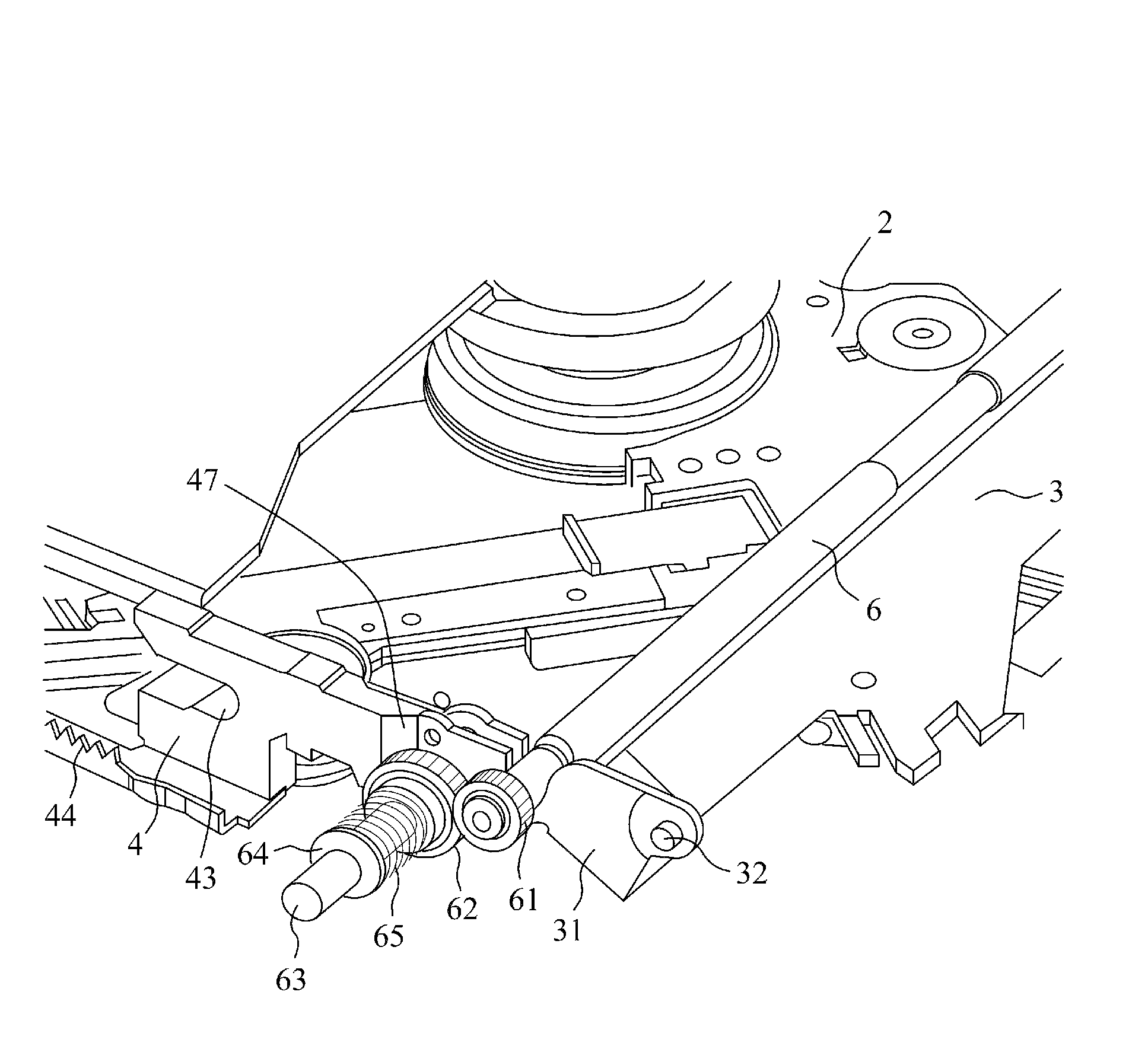
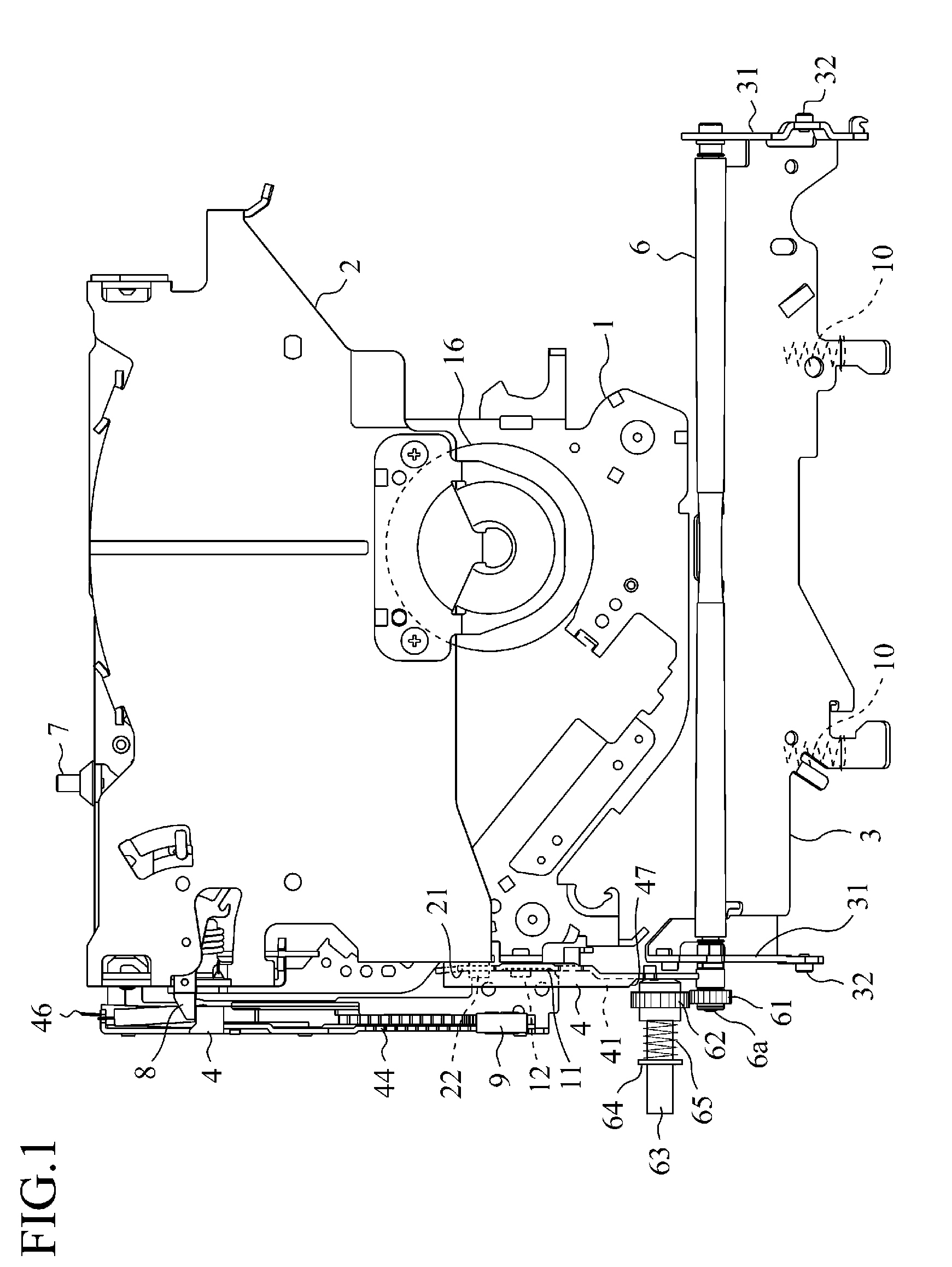
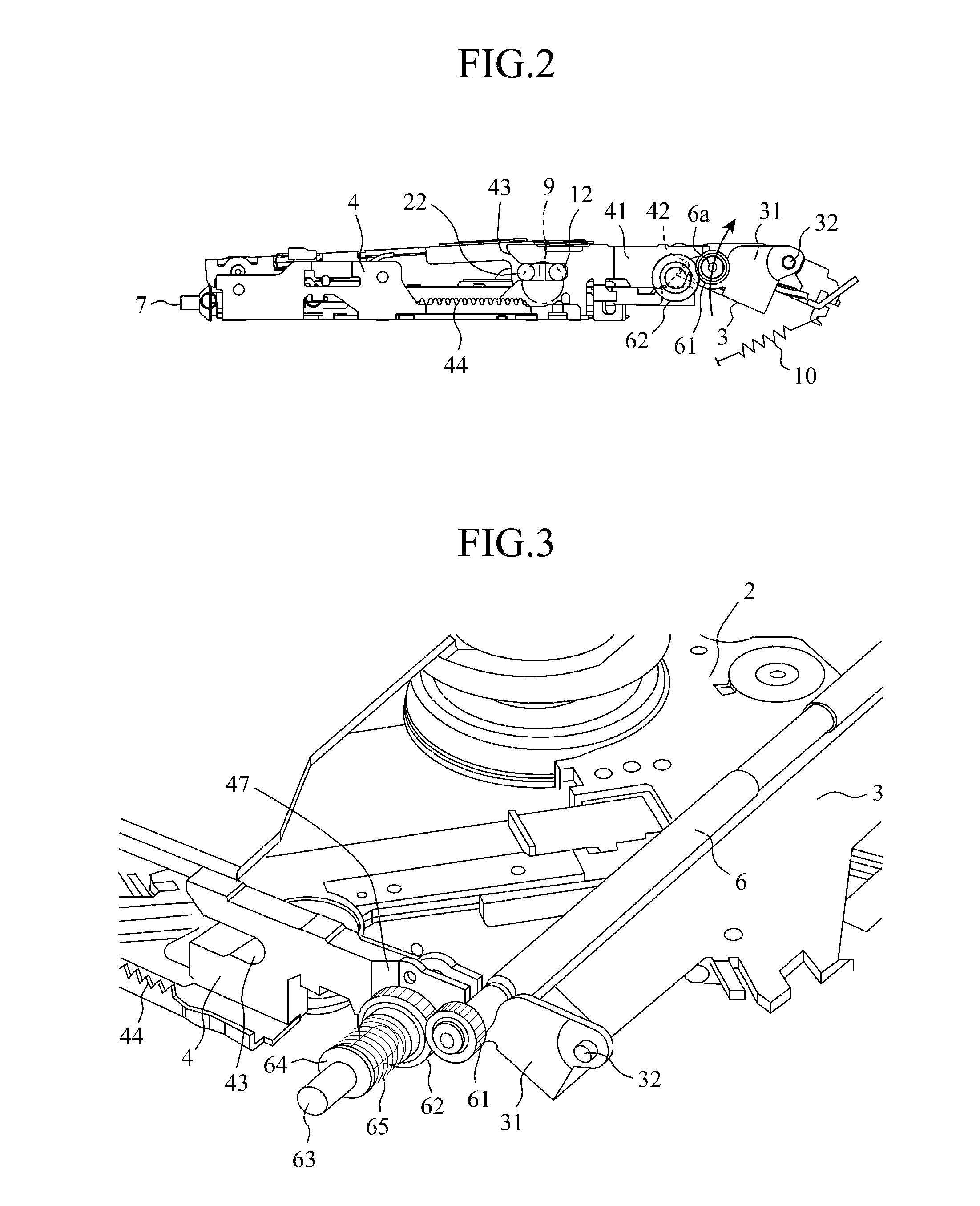
[0027]FIG. 1 is a plan view showing only the main part in a standby condition for disk loading in a disk reproducing apparatus in accordance with a first embodiment of the present invention, FIG. 2 is a left side view of FIG. 1, FIG. 3 is a perspective view of a conveyance roller drive shown in FIG. 1, FIG. 4 is a plan view of FIG. 3, FIG. 5 is a perspective view of an essential part showing a state after completion of a disk carrying operation, FIG. 6 is a plan view of FIG. 5, FIG. 7 is a plan view showing only the main part in a disk reproducing state, FIG. 8 is a left side view of FIG. 7, FIG. 9 is a perspective view of a conveyance roller drive shown in FIG. 7, and FIG. 10 is a plan view of FIG. 9.

[0028]A disk device in accordance with the first embodiment of the present invention includes a reproducing base 1, an arm clamp 2, a roller base member 3, and a slider member 4. The reproducing base 1 is provided to be locked on or unlocked from a chassis board through a support membe...

second embodiment

[0039]In the first embodiment discussed above, the disk device is arranged such that the cam section 47 for pushing and moving the drive gear 62 in a thrust direction against the urging force of the coil spring 65 is provided on the side of the perpendicularly bent side plate 41 of the slider member 4. However, in the second embodiment, as shown to FIG. 11, one face of a drive gear 62, namely, the face against which a slider member 4 abuts, is formed in a conical shape 62a.

[0040]According to the aforementioned structure, when the forward end of the slider member 4 moves with abutting the conical face 62a of the drive gear 62, the drive gear 62 is moved in a thrust direction to be unmeshed from the rotation gear 61. As a result, an action effect similar to that of the first embodiment is obtained without providing a special cam section 47 on the slider member 4.

third embodiment

[0041]In the third embodiment shown in FIG. 12, a convex 34 that abuts against a drive gear 62 in the process pushed and moved by a slider member 4 is provided on a roller base member 3 for supporting a conveyance roller 6, and either the drive gear 62 or the convex 34 is formed in a slope shape (a conical face 62a). According to such a structure, in the process where the roller base member 3 is forced downwardly by the slider member 4 forwardly moving, the drive gear 62 is moved in a thrust direction by abutting against the convex 34 to be unmeshed from the rotation gear 61. Thus, an action effect similar to that of the second embodiment is obtained.


PUM

PropertyMeasurementUnit
movementaaaaaaaaaa
conical shapeaaaaaaaaaa
rotation driving forceaaaaaaaaaa

Abstract

A disk device includes: a slider member 4 to be pushed and moved by the movement of a disk detection member 8 detecting the loading of a disk when the disk 5 is loaded in a predetermined position of a device body; a drive gear 62 moved in a thrust direction by the movement of the slider member 4 to be unmeshed from a rotation gear 61 integral with a conveyance roller 6; and a coil spring 65 that normally urges the drive gear 62 in a direction meshing with the rotation gear 61.

Description

TECHNICAL FIELD[0001]The present invention relates to a disk device for loading and unloading a disk into and from a device body with a conveyance roller.BACKGROUND ART[0002]In conventional disk devices, for example, as disclosed in Patent Document 1, when a disk is carried to a reproducing position where the disk is loaded onto a turntable by rotation of a conveyance roller, a slider member is pushed and moved toward the front side of a device parallel to the carrying direction of the disk by the movement of a disk detection member that detects the loading of the disk. The disk is clamped on the turntable by the movement of the slider member, further a reproducing base is unlocked from a chassis that is a device body to go to a state of disk reproduction. At that time, a roller base member for supporting the conveyance roller is also in engagement with the slider member, and the roller base member rotates about a rotation shaft by the movement of the slider member. Thus, the convey...

Claims


Application Information

Patent Timeline
Patent Type & Authority Patents(United States)
IPC IPC(8): G11B17/04
CPCG11B17/051
Inventor SUZUI, YUICHIRO
Owner MITSUBISHI ELECTRIC CORP
Learn More