
Spectroscope

a spectroscope and spectrometer technology, applied in the field of spectroscopes, can solve the problems of short response time, long response time required for varying wavelengths, and large size of the device, and achieve the effect of short response time and reduced device siz

Active Publication Date: 2011-03-10
NIPPON TELEGRAPH & TELEPHONE CORP
View PDF2 Cites 2 Cited by
  • Summary
  • Abstract
  • Description
  • Claims
  • Application Information

AI Technical Summary

Benefits of technology

[0012]To resolve these problems, one objective of the present invention is to provide a small spectroscope that has a short response time.
[0014]According to the first embodiment, since the beam deflector, which includes the electro-optic crystal having an electro-optic effect, the spectroscopic means and the wavelength selection means are prepared, a short response time and downsizing of the device can be provided.
[0015]According to a second embodiment, the opening in the beam deflector is enlarged for the purpose of increasing the sensitivity of the spectroscope, in addition to a reduction in the response time and in the size of the spectroscope. That is, according to the second embodiment, the spectroscope of the first embodiment is further characterized in that the width of the beam deflector is greater than the thickness of the beam deflector. Furthermore, the spectroscope of the second embodiment may further include means for projecting, to the beam deflector, light having an elliptic shape, in cross section. In this instance, the light having the elliptic shape, in cross section, enters the beam deflector, so that a direction along the long axis of the elliptic shape matches the direction of the width.
[0022]Also, the objectives of a fifth embodiment are the acquisition of a high resolution without increasing the angle of the deflection of light that is output by a beam deflector, which includes an electro-optic crystal having an electro-optic effect, and a reduction in a required voltage that is to be applied to the beam deflector to obtain a predetermined resolution. To achieve these objectives, a difference in optical path lengths is increased between a beam, deflector and spectroscopic means, such as a prism or a diffraction grating.
[0032]According to the present invention, since the beam deflector, which includes an electro-optic crystal having an electro-optic effect, the spectroscopic means and the wavelength selection means are prepared, a short response time and downsizing of the device can be obtained.

Problems solved by technology

However, a problem exists in that the conventional spectroscopes in FIGS. 1 and 2 must include a mechanical control units, such as a motor for mechanically rotating either a prism or a diffraction grating, whichever serves as the spectroscopic means, and a drive circuit for driving the motor, and that the structure of the spectroscopes is increased.
Here also, another problem exists in that since this operation is performed mechanically, the response time required for varying a wavelength is long, and several ms are required.
Since a heat control mechanism is also required to supply the electric power and to cope with the heat that is generated, another problem is that downsizing of the device can not be attained.
Furthermore, another defect is that the response time for varying a wavelength is long, i.e., 2 to 60 ms, because the thermo-optic effect is employed.

Method used


Image

  • Spectroscope
  • Spectroscope
  • Spectroscope

Examples


first embodiment

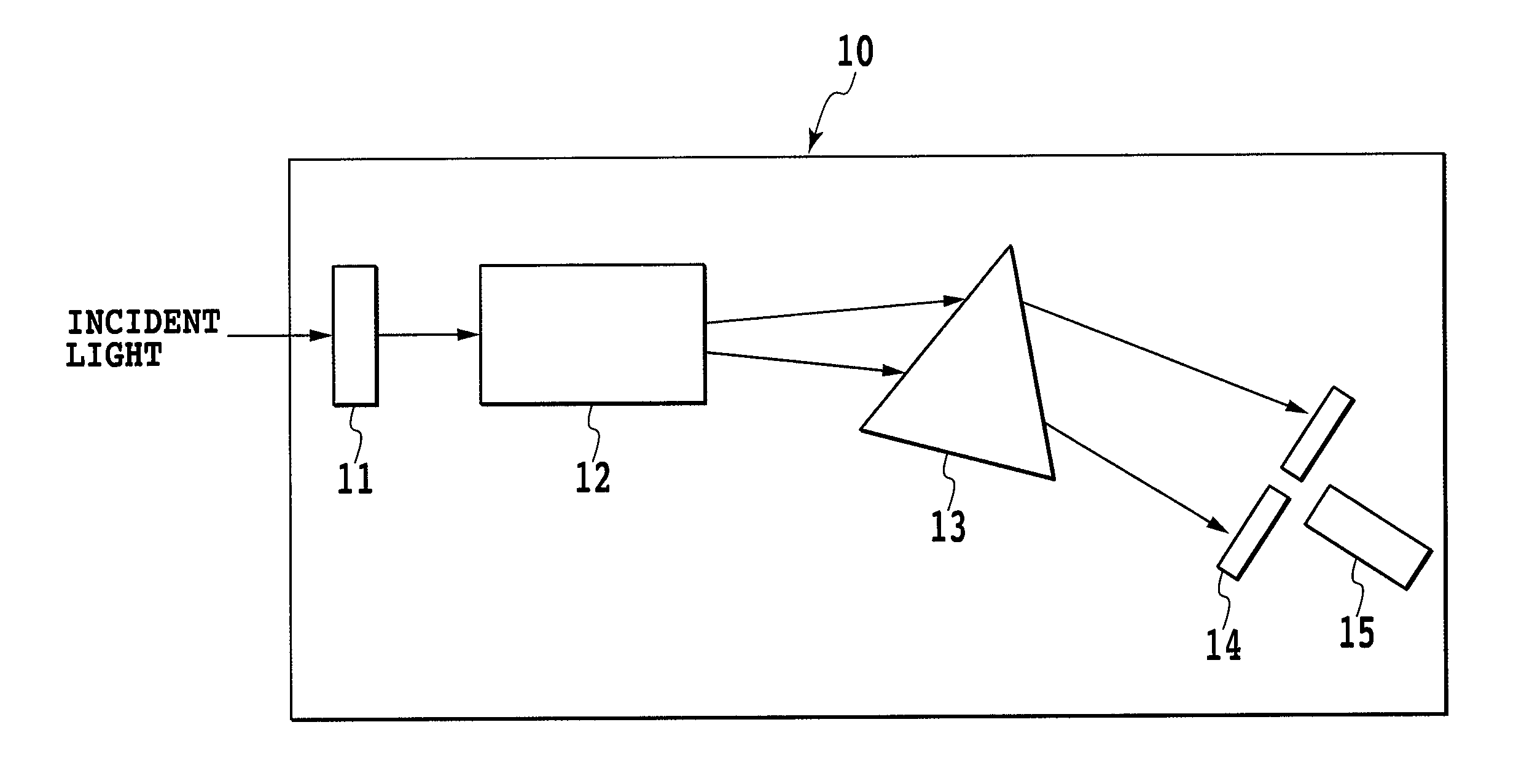
[0058]The objective of the present invention is to provide a spectroscope for which the response time and the device size can be reduced, when compared with a conventional one. To achieve this objective, according to one embodiment of the present invention, a beam deflector that deflects incident light, using an electro-optic crystal having an electro-optic effect, and outputs the deflected light is located upstream of a prism or a diffraction grating, which serves as spectroscopic means, in a direction in which dispersed light advances. FIG. 4 is a diagram illustrating the structure of a spectroscope having such an arrangement.

[0059]In FIG. 4, a spectroscope 10 includes a polarizer 11 that polarizes incident light, a beam deflector 12 formed of a crystal having an electro-optic effect, a prism 13 that serves as spectroscopic means, a slit plate 14 that serves as wavelength selection means, and a photodetector 15.

[0060]Example crystals having a large electro-optic constant are the f...

second embodiment

[0079]A spectroscope for a second embodiment of the present invention is shown in FIG. 8 to provide a short time response and a small-sized device. A spectroscope 40 includes a deflection plate 41, which controls the deflection of incident light, a beam deflector 42, which is formed of a crystal having an electro-optic effect, a diffraction grating 43, which serves as spectroscopic means, a slit plate 44, which serves as wavelength selection means, and a photodetector 45. In this embodiment, a diffraction grating is employed as spectroscopic means, instead of the prism used in the first embodiment.

[0080]The diffraction grating 43 is a square with 20 mm sides, and 150 grooves / mm are formed in the surface. The length of an optical path, extending from the beam deflector 42 to the diffraction grating 43, is 20 mm. However, when a diffraction grating 43 having a smaller size is employed, the length of the optical path can be shortened.

[0081]Assume that the wavelength range of incident l...

third embodiment

[0087]In this embodiment, an explanation will be given for a spectroscope that employs a prism, as spectroscopic means (a spectroscopic medium), with which a high resolution can be obtained without increasing the deflection angle for light output by a beam deflector, which includes an electro-optic crystal having an electro-optic effect, and for which, to acquire a predetermined resolution, a voltage applied to the beam deflector can be reduced.

[0088]FIG. 9 is a diagram for explaining the principle of spectroscopy for the first embodiment.

[0089]In FIG. 9, reference numeral 131 denotes the apex of a prism 13, and reference numeral 132 denotes the output plane of the prism 13, through which the light projected by the beam deflector 12 is output. Reference numeral 134a denotes light (also called output light 134a), which is part of the light output by the prism 13 under a first voltage applied state of the beam deflector 12, that has the longest wavelength in a desired wavelength range...


PUM


Abstract

The present invention provides a small spectroscope that has a short response time. A spectroscope according to one embodiment of the present invention includes: a beam deflector that includes an electro-optic crystal, having an electro-optic effect, and paired electrodes used to apply an electric field inside the electro-optic crystal; spectroscopic means for dispersing light output by the beam deflector; and wavelength selection means for selecting light having an arbitrary wavelength from the light dispersed and output by the spectroscopic means.

Description

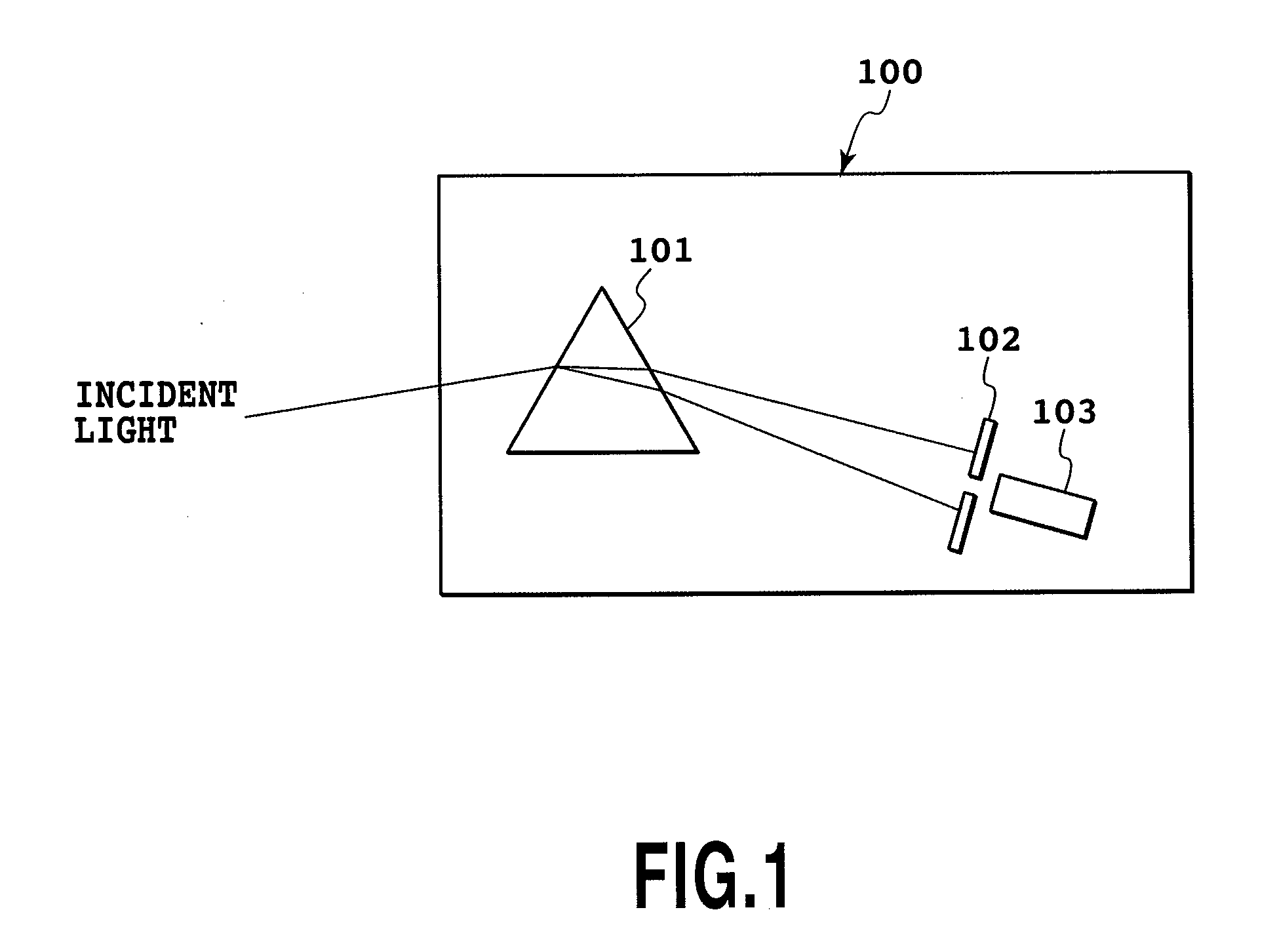
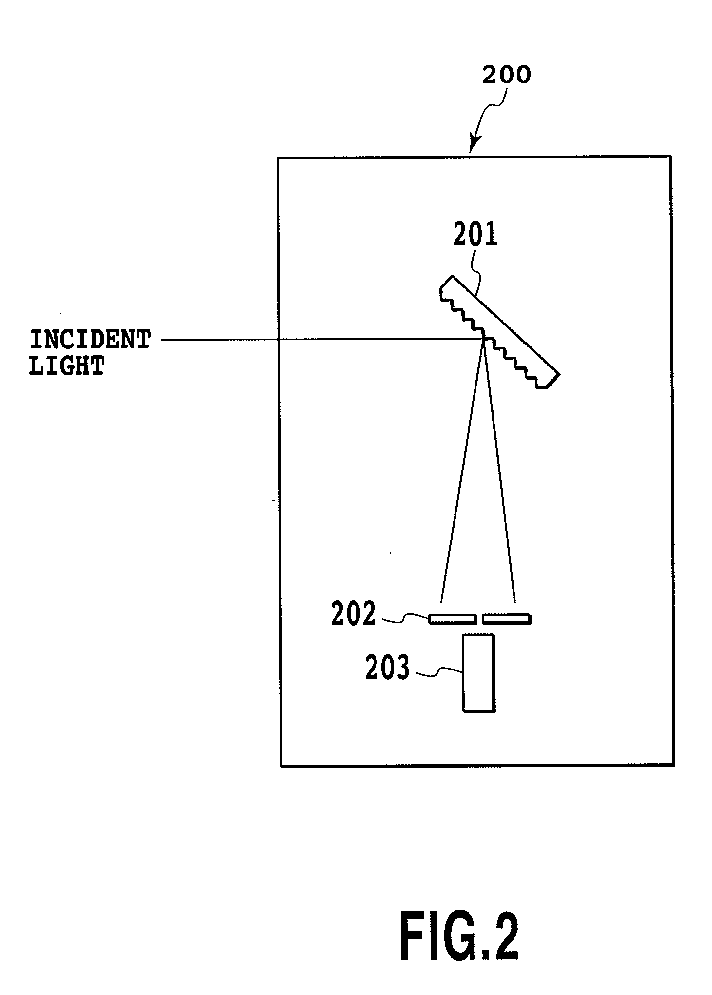
TECHNICAL FIELD[0001]The present invention relates to a spectroscope, and more particularly to a spectroscope for selecting an optical signal having an arbitrary wavelength.BACKGROUND ART[0002]A spectroscope is employed for a device for measuring spectral characteristics of substances, such as absorption spectrums and fluorescence spectrums (see non-patent document 1).[0003]A conventional spectroscope employing a prism is shown in FIG. 1. This spectroscope 100 includes a prism 101, which serves as spectroscopic means, a slit plate 102, which serves as wavelength selection means, and a photodetector 103.[0004]A conventional spectroscope employing a diffraction grating is shown in FIG. 2. This spectroscope 200 includes a diffraction grating 201, which serves as spectroscopic means, a slit plate 202, which serve as wavelength selection means, and a photodetector 203.[0005]Referring to FIGS. 1 and 2, wavelength dispersion elements, such as the prism 101 and the diffraction grating 201, ...

Claims


Application Information

Patent Timeline
Patent Type & Authority Applications(United States)
IPC IPC(8): G01J3/447G01J3/28
CPCG01J3/02G01J3/0205G01J3/0237G01J2003/064G01J3/14G01J3/18G01J3/36G01J3/06
Inventor NAKAMURA, KOICHIROSASAKI, YUZOFUJIURA, KAZUOYAGI, SHOGO
Owner NIPPON TELEGRAPH & TELEPHONE CORP
Learn More