
Variable valve timing device and method of assembling same

a valve timing and variable technology, applied in the direction of valve arrangements, machines/engines, mechanical equipment, etc., can solve the problems of increasing the number of parts, increasing the time for assembly, increasing the cost, etc., and achieves the reduction of wear and friction force in the sliding area, the effect of simplifying the structure and reducing the number of components

Active Publication Date: 2015-12-17
MIKUNI CORP
View PDF2 Cites 4 Cited by
  • Summary
  • Abstract
  • Description
  • Claims
  • Application Information

AI Technical Summary

Benefits of technology

The valve timing varying device described in the patent has the following benefits: preventing the vane rotor from tilting, reducing wear and friction in the sliding area, ensuring a predetermined function, simplifying the assembly process, reducing the number of components, making the device thinner and more compact, and lowering the cost.

Problems solved by technology

Therefore, the number of parts is increased, the man-hour for assembling is increased, and it causes an increase in cost.
Therefore, it is not easy to assemble the front side cover member to the cylindrical member while latching the one end of the torsion spring on the vane rotor and latching the another end of the torsion spring on the housing rotor (the front side cover member).
Furthermore, in case that a two-divided structure that the cylindrical member and the front side cover member are integrally formed is adopted for simplification of the structure, it is more difficult to assemble the torsion spring.
Further, since the fixed pin for latching (or hooking) on the another end of the assist spring is provided on the front face of the outer side of the housing rotor, a size of the device as a whole in the direction of the rotation axis becomes larger, a requirement of downsizing is not met.
Furthermore, since the cylindrical bushing for accommodating the coil part of the assist spring and the fixed pin provided on the housing rotor and the like are required, there arise problems such that components accompanying the assist spring increase, the structure becomes more complex, and the cost becomes higher.

Method used


Image

  • Variable valve timing device and method of assembling same
  • Variable valve timing device and method of assembling same
  • Variable valve timing device and method of assembling same

Examples


Embodiment Construction

[0050]Hereinafter, embodiments of the present invention will be described with reference to the attached drawings.

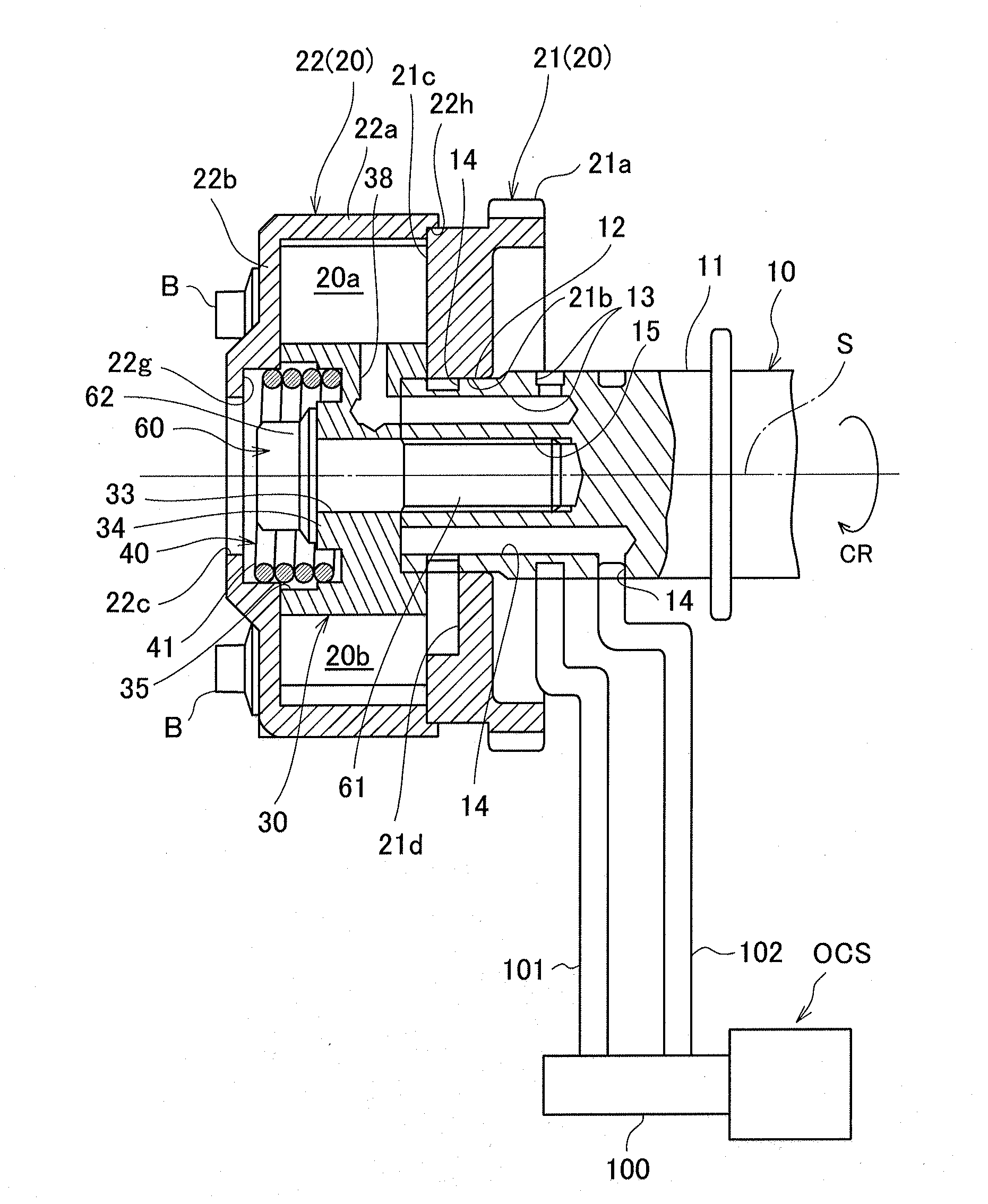
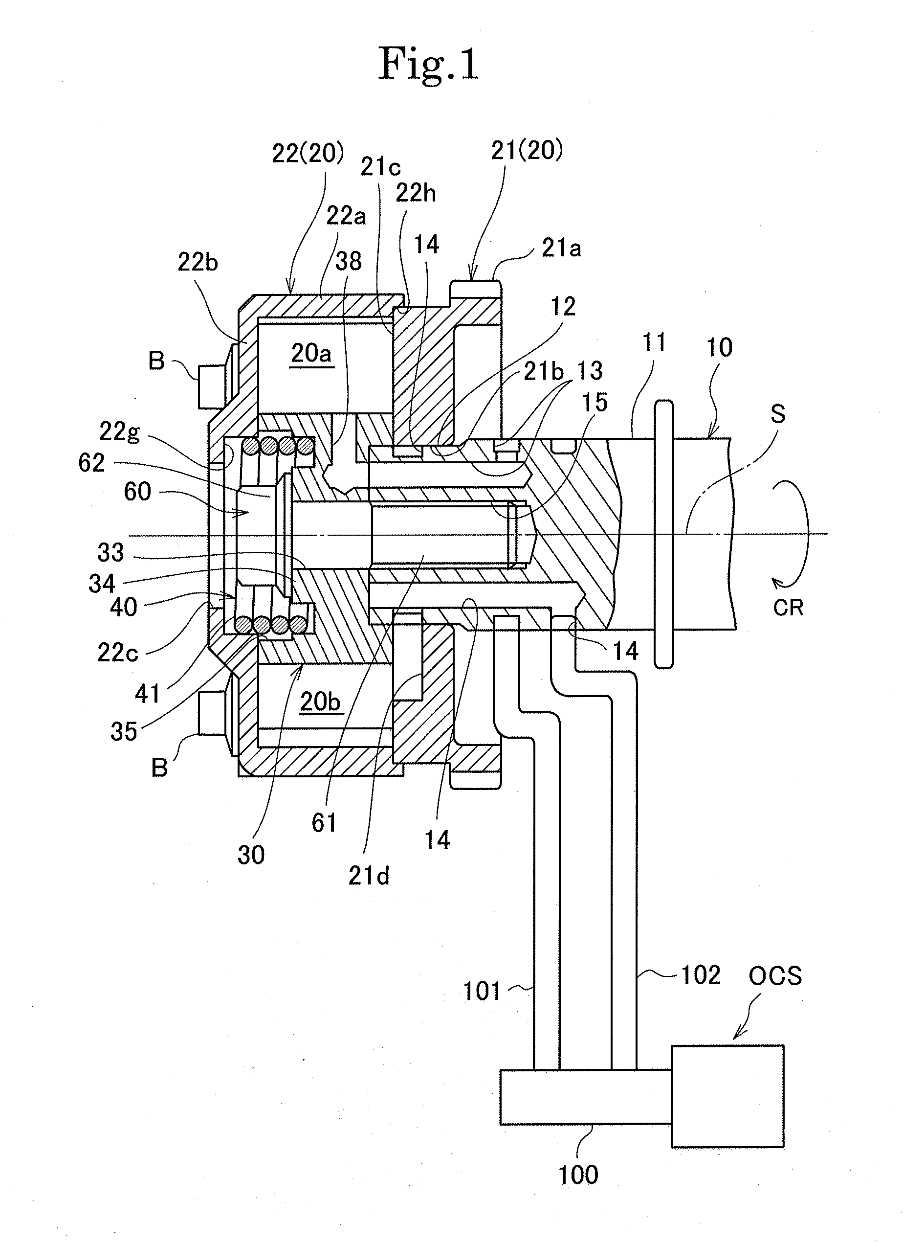
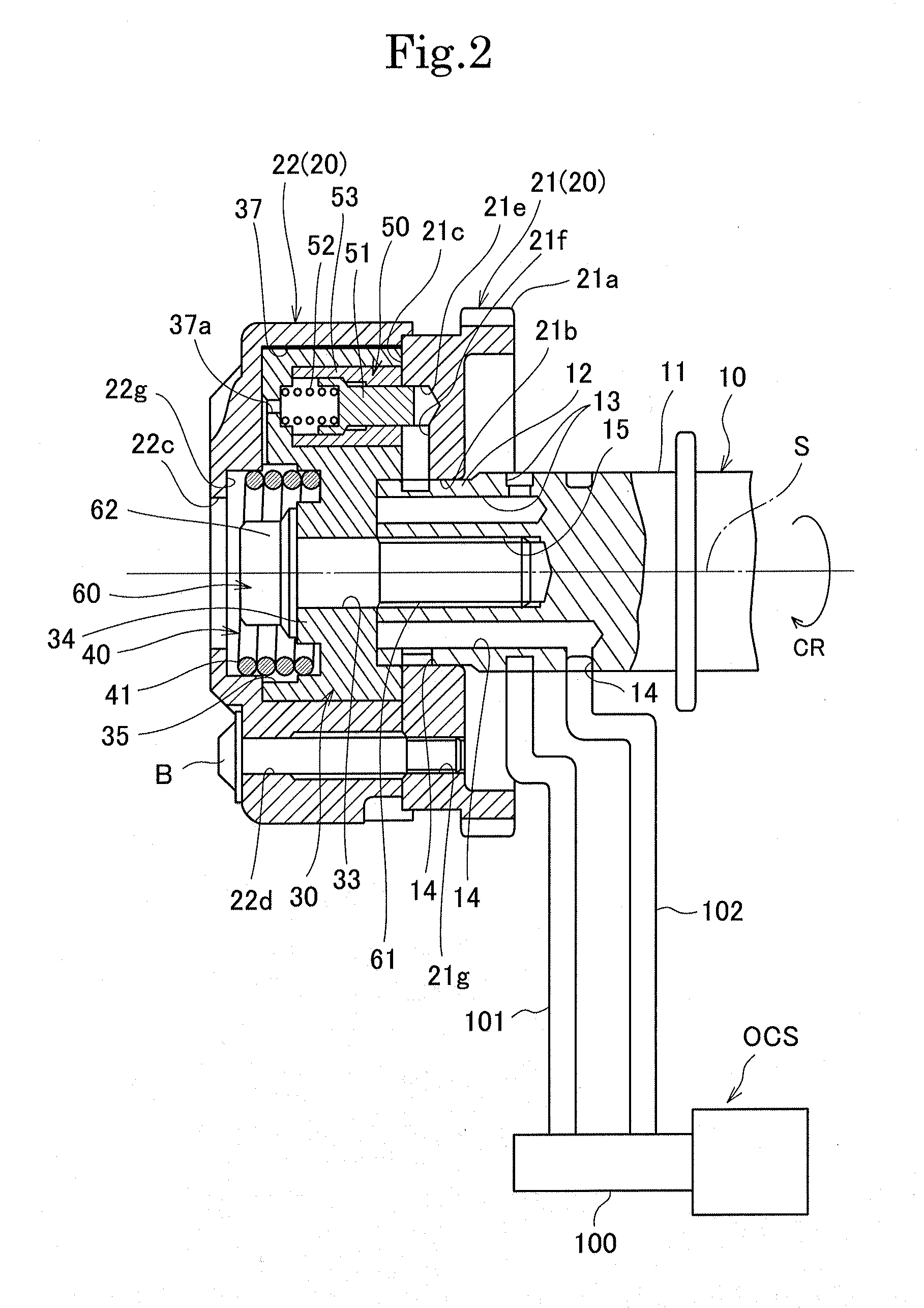
[0051]This valve timing varying device includes, as shown in FIG. 1 to FIG. 4, a housing rotor 20 rotated on a rotation axis S of a camshaft 10, a vane rotor 30 detachably fixed to the camshaft 10 so as to be rotated integrally with the camshaft 10 and accommodated in an accommodating chamber of the housing rotor 20 so as to relatively rotate within a predetermined angle range Δθ (see FIG. 10) to divide the accommodating chamber into an advanced angle chamber 20a and a retarded angle chamber 20b, a torsional coiled urging spring 40 (which has a coil part 41, a first end 42, and a second end 43) for rotation-urging the vane rotor 30 toward one rotation direction (here, toward an advanced angle direction) relative to the housing rotor 20, a lock mechanism 50 for locking the vane rotor 20 with respect to the housing rotor 20 in a predetermined angle position (here, in a mos...


PUM

PropertyMeasurementUnit
Diameteraaaaaaaaaa
Areaaaaaaaaaaa

Abstract

The valve timing varying device according to the present invention includes a housing rotor (20) composed of a front side housing member (22) and a rear side housing member (21), a vane rotor (30), and an urging spring (40) for rotationally urging the vane rotor in one direction with respect to the housing rotor. The urging spring (40) has a coil part (41), a first end (42) provided outside in a radial direction with respect to the coil part, and a second end (43) provided inside in the radial direction with respect to the coil part. The front side housing member (22) has a first latching concave part (22f) for latching the first end on an inside wall face. The vane rotor (30) has an accommodation concave part (35) for accommodating at least a part of the coil part at the front end side, and a second latching concave part (36) for latching the second end in an area facing an opening (22c). Therefore, wear and a friction force in a sliding area can be reduced and the assembling performance can be improved while achieving the size reduction of the device.

Description

TECHNICAL FIELD[0001]The present invention relates to a valve timing varying device which varies an opening and closing timing (valve timing) of an intake valve or an exhaust valve of an internal combustion engine in response to driving conditions, and a method of assembling thereof.BACKGROUND ART[0002]As a conventional valve timing varying device, there is known a valve timing varying device including a housing rotor (a driving-side rotor) rotated in synchronism with a crankshaft, a vane rotor (a driven-side rotor) rotated in synchronism with a camshaft and accommodated in the housing rotor to divide an accommodating chamber thereof into a retarded angle chamber and an advanced angle chamber and relatively rotatable relative to the housing rotor within a predetermined operating angle (an angle range between a most advanced angle position and a most retarded angle position), a coiled torsion spring installed between the housing rotor and the vane rotor in order to rotation-urge the ...

Claims


Application Information

Patent Timeline
IPC IPC(8): F01L1/344
CPCY10T29/493F01L1/344F01L1/3442F01L2001/34469F01L2001/34483F01L2303/00
Inventor SUGANO, KOJINAKANISHI, RYO
Owner MIKUNI CORP
Learn More