Optical fiber, fiber laser, and optical fiber manufacturing method

Inactive Publication Date: 2015-09-03
PANASONIC INTELLECTUAL PROPERTY MANAGEMENT CO LTD
View PDF3 Cites 3 Cited by
  • Summary
  • Abstract
  • Description
  • Claims
  • Application Information

AI Technical Summary

Benefits of technology

[0017]According to the configuration, the scattering loss amount of the pumping light from collectively recoated

Problems solved by technology

However, the viewpoint of minimizing the length of the recoa

Method used


Image

  • Optical fiber, fiber laser, and optical fiber manufacturing method
  • Optical fiber, fiber laser, and optical fiber manufacturing method
  • Optical fiber, fiber laser, and optical fiber manufacturing method

Examples


first exemplary embodiment

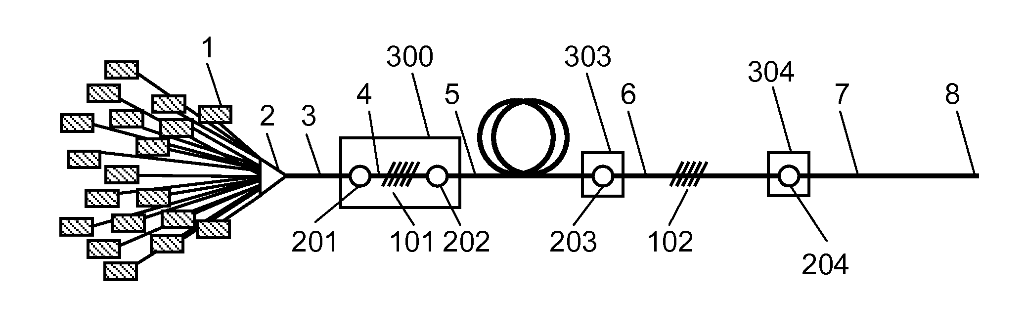
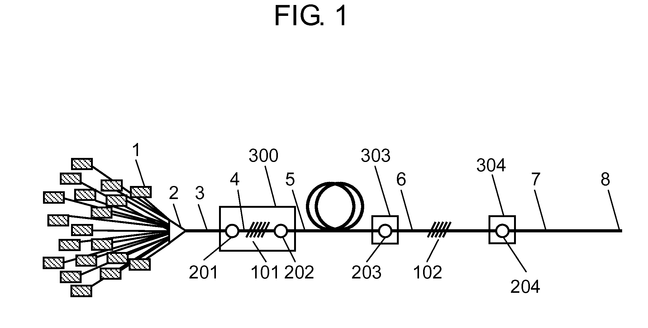
[0022]FIG. 1 is an entire configuration diagram of a fiber laser in which an optical fiber of the present invention is used. FIG. 2 is an enlarged sectional view illustrating a detailed configuration of collectively recoated portion 300 that is a main part of the optical fiber of the present invention.

[0023]As illustrated in FIG. 1, pumping light beams (not illustrated) emitted from a plurality of pumping laser diodes 1 are introduced to pumping light introduction fiber 3 through pumping light coupler 2. Pumping light introduction fiber 3 is a double clad fiber propagating the pumping light.

[0024]Active fiber 5 serving as a double clad fiber is placed. A rare-earth element is added to a core portion of active fiber 5, high-reflection FBG fiber 4 in which high-reflection FBG 101 is written is provided on a pumping light input side of active fiber 5, and low-reflection FBG fiber 6 in which low-reflection FBG 102 is written is provided on the other end. Active fiber 5 is sandwiched bet...

example

[0065]An experiment was specifically performed as an example using the fiber laser and optical fiber of the first exemplary embodiment having the configurations in FIGS. 1 and 2. The detailed example and a measurement result of pumping light transmittance are described below.

[0066]19 laser diodes of L4-9891510-100C produced by JDSU were used as pumping laser diode 1, and a 19×1 combiner produced of Lightcomm was used as pumping light coupler 2.

[0067]A FUD-3386 fiber produced by Nufern was used as pumping light introduction fiber 3, high-reflection FBG fiber 4 that was shortened while the coating was removed, low-reflection FBG fiber 6, and output fiber 7.

[0068]A SM-YDF-7 / 210 fiber (produced by Nufern) of 50 m was used as active fiber 5 while wound around an aluminum reel of φ150 mm to radiate the heat.

[0069]High-reflection FBG fiber 4 that was shortened while the coating was removed had the total length of 15 mm, and collectively recoated portion 300 has the length of 55 mm. A cente...


PUM

PropertyMeasurementUnit
Refractive indexaaaaaaaaaa
Optical reflectivityaaaaaaaaaa

Abstract

An optical fiber of the present invention includes an uncoated FBG fiber in which an FBG mirror is written in a core glass, a first optical fiber that is spliced to one end of the FBG fiber with a first spliced point interposed therebetween, and a second optical fiber that is spliced to the other end of the FBG fiber with a second spliced point interposed therebetween. The optical fiber of the present invention also includes a collectively recoated portion in which at least the FBG fiber, the first spliced point, and the second spliced point are collectively recoated with a recoat resin having a refractive index less than that of silica, the FBG fiber being sandwiched between the first spliced point and the second spliced point.

Description

TECHNICAL FIELD [0001]The present invention relates to a configuration of an optical fiber used in a fiber laser and, particularly to an optical fiber having a fusion-spliced and recoated structure of a double clad fiber, a fiber laser in which the optical fiber is used, and an optical fiber producing method.BACKGROUND ART [0002]A general fiber laser includes a pumping light source, a laser active fiber, and FBG mirrors placed on both sides of the optical fiber to construct a resonator, and each optical fiber is fusion-spliced (for example, see Unexamined Japanese Patent Publication No. 2010-238709).[0003]As to a recoated structure of a fusion-spliced point of a double clad fiber in the fiber laser, a technology of recoating a fusion-spliced point formed by fusion-splicing ends of two optical fibers with a low-refractive-index resin and coating a recoated portion with a reinforcing sleeve and a technology of forming a recoated portion having a substantially conical shape have been p...

Claims


Application Information

Patent Timeline
IPC IPC(8): G02B6/255H01S3/067H01S3/094G02B6/02
CPCG02B6/255G02B6/02076G02B6/02123H01S3/094042H01S3/0675G02B6/02209G02B6/2558H01S3/09408H01S3/094007
Inventor ITOH, HIDEAKI
Owner PANASONIC INTELLECTUAL PROPERTY MANAGEMENT CO LTD
Why Eureka
Try Eureka