Power Reception Device and Power Transmission Device

a power reception device and power transmission technology, applied in the direction of instruments, process and machine control, baseband system details, etc., can solve the problems of reducing the adverse effect of the electric field, reducing the unnecessary radiation of the high voltage side conductor,

Active Publication Date: 2012-11-15
MURATA MFG CO LTD
View PDF10 Cites 4 Cited by
  • Summary
  • Abstract
  • Description
  • Claims
  • Application Information

AI Technical Summary

Benefits of technology

[0008]Accordingly, it is an object of the present invention to provide a configuration which enables the power reception device and the power transmission device to be incorporated in an actual device and which is capable of suppressing an adverse effect of an electric field.
[0019]According to the present invention, it is possible to protect the active part which is susceptible to an electric field generated from the high voltage side conductor by the low voltage side conductor, thereby to suppress the adverse effect of the electric field. When all the module parts are disposed on the opposite side away from the high voltage side conductor, the distance between the high voltage side conductor and the low voltage side conductor can be shortened, which leads to downsizing of the device.
[0021]Since the low voltage side conductor is formed to surround the high voltage side conductor in a plane, unnecessary radiation from the high voltage side conductor can be reduced.
[0022]Further, since the secondary battery serving as the load in the power reception device is disposed on the opposite side away from the high voltage side conductor with respect to the low voltage side conductor, it is possible to protect the circuit inside the battery from the electric field generated from the high voltage side conductor, thereby to reduce the adverse effect of the electric field.

Problems solved by technology

However, Patent Literature 1 discloses no specific configuration to be incorporated in a device.

Method used


Image

  • Power Reception Device and Power Transmission Device
  • Power Reception Device and Power Transmission Device
  • Power Reception Device and Power Transmission Device

Examples


first embodiment

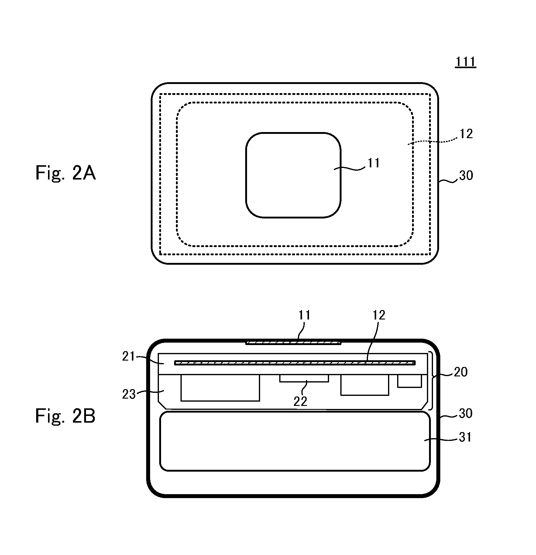
[0031]The configuration of a power reception device according to a First Embodiment will be described with reference to FIGS. 2A, 2B and 3.

[0032]FIG. 2A is a top plan view illustrating a power reception device 111, and FIG. 2B is a sectional view of the power reception device. For the purpose of avoiding complication in these figures, hatching is omitted from the sectional view except electrode portions.

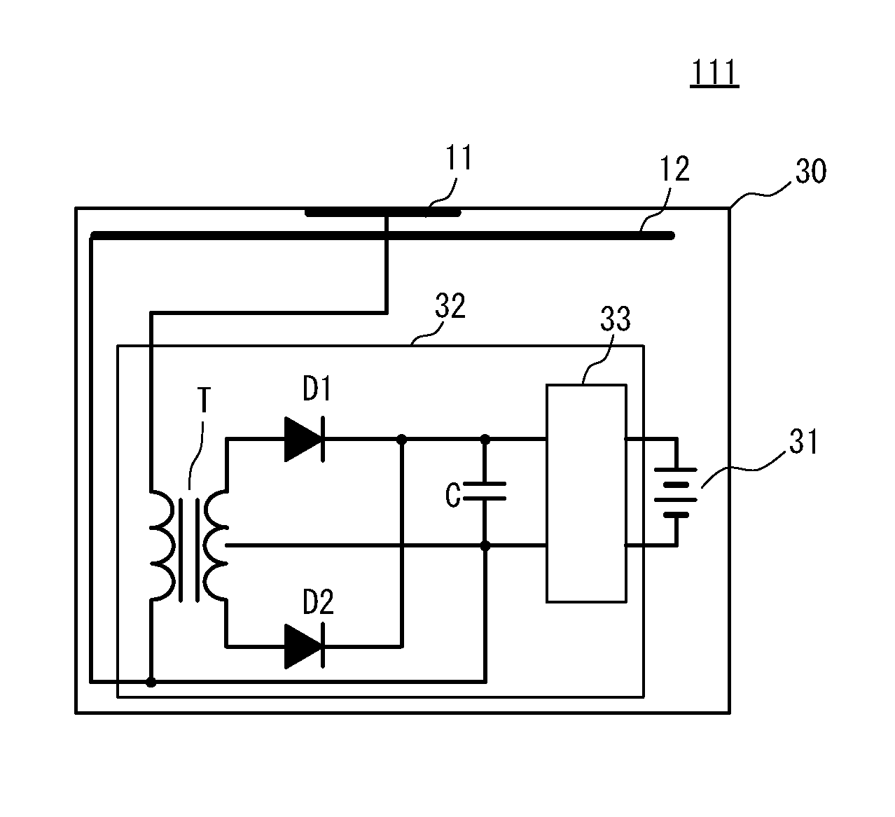
[0033]The power reception device 111 includes a capacitive coupling electrode to be coupled to a capacitive coupling electrode of a non-illustrated power transmission device. The capacitive coupling electrode of the power reception device 111 comprises a high voltage side conductor 11 shown in FIGS. 2A-2B and a low voltage side conductor 12 extending around the high voltage side conductor 11.

[0034]The power reception device 111 includes an electrically insulating housing 30. In the example shown, the high voltage side conductor 11 is disposed on a surface of the housing 30. The low v...

second embodiment

[0046]The configuration of a power reception device according to a Second Embodiment will be described with reference to FIGS. 4A and 4B.

[0047]FIG. 4A is a top plan view illustrating a power reception device 112, and FIG. 4B is a sectional view of the power reception device. For the purpose of avoiding complication in these figures, hatching is omitted from the sectional view except electrode portions.

[0048]The power reception device 112 includes a capacitive coupling electrode to be coupled to a capacitive coupling electrode of a non-illustrated power transmission device. The capacitive coupling electrode of the power reception device 112 comprises a high voltage side conductor 11 shown in FIGS. 4A-4B and a low voltage side conductor 12 extending around the high voltage side conductor 11.

[0049]In the example shown, the high voltage side conductor 11 which is in a state of being encapsulated with a molding resin 24 is integrated with a circuit board 21. The low voltage side conducto...

third embodiment

[0052]Several power reception devices having different configurations according to a Third Embodiment will be described with reference to FIGS. 5A-5D.

[0053]FIGS. 5A-5D is a sectional view illustrating power reception devices 113 to 116. For the purpose of avoiding complication in these figures, hatching is omitted from each of the sectional views except electrode portions. Any one of the power reception devices 113 to 116 includes a high voltage side conductor 11 and a low voltage side conductor 12 which are formed in a multilayer board 25. A plurality of module parts 22 are mounted on a surface of the multilayer board 25 which is located on the opposite side away from the high voltage side conductor 11 with respect to the low voltage side conductor 12.

[0054]The high voltage side conductors 11 of the respective power reception devices 113 and 114 are each formed at an internal layer of the multilayer board 25. The high voltage side conductors 11 of the respective power reception dev...


PUM


Abstract

A power reception device and a power transmission device which are capable of suppressing an adverse effect of an electric field. A power reception device includes a capacitive coupling electrode comprising a high voltage side conductor and a low voltage side conductor extending around the high voltage side conductor. The high voltage side conductor is disposed on a surface of a housing. The low voltage side conductor is disposed inside a circuit board. A plurality of module parts are mounted on a surface of the circuit board which is located on an opposite side away from the high voltage side conductor with respect to the low voltage side conductor.

Description

CROSS REFERENCE TO RELATED APPLICATIONS[0001]The present application is a continuation of International application No. PCT / JP2011 / 051725, filed Jan. 28, 2011, which claims priority to Japanese Patent Application No. 2010-017568, filed Jan29, 2010, the entire contents of each of which are incorporated herein by reference.FIELD OF THE INVENTION[0002]The present invention relates to a power reception device and a power transmission device which transfers electric power in a noncontact manner.BACKGROUND OF THE INVENTION[0003]Patent Literature 1 discloses a system configured to transfer electric power through capacitive coupling.[0004]The power transfer system described in Patent Literature 1 comprises: a power transmission device including a high-frequency high-voltage generator, a passive electrode, and an active electrode; and a power reception device including a high-frequency high-voltage load, a passive electrode, and an active electrode.[0005]FIG. 1 is a view illustrating the bas...

Claims


Application Information

Patent Timeline
Patent Type & Authority Applications(United States)
IPC IPC(8): H02M3/06H02J7/00
CPCH02J7/025H04B5/0037H02J17/00H04B5/0012H02J50/05H02J50/10H02J7/0042H02J50/70H04L25/0266
Inventor ICHIKAWA, KEIICHIBONDAR, HENRI
Owner MURATA MFG CO LTD
Why Eureka
Try Eureka