

Belt molding for vehicles
a technology for belts and wing clips, applied in doorways, wing accessories, transportation and packaging, etc., can solve the problems of dirt and/or water droplets deteriorating the wipe-off function of seal lips, difficult to return the seal lip to its original position, and inability to perform favorable wiping operations in some cases
- Summary
- Abstract
- Description
- Claims
- Application Information
AI Technical Summary
Benefits of technology
Problems solved by technology
Method used
Image

Examples
first embodiment
[0095]An outer belt molding according to a first embodiment of the present invention will be explained with reference to FIGS. 1 to 5.
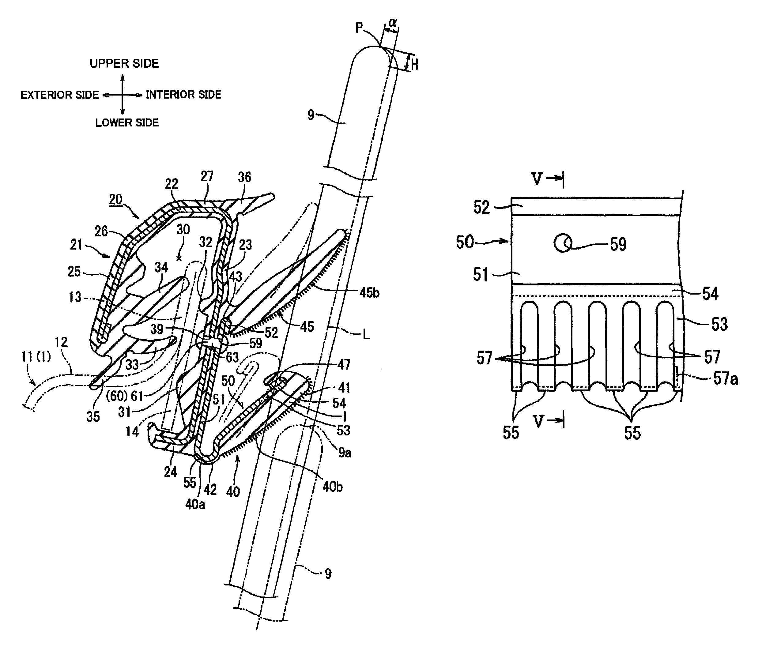
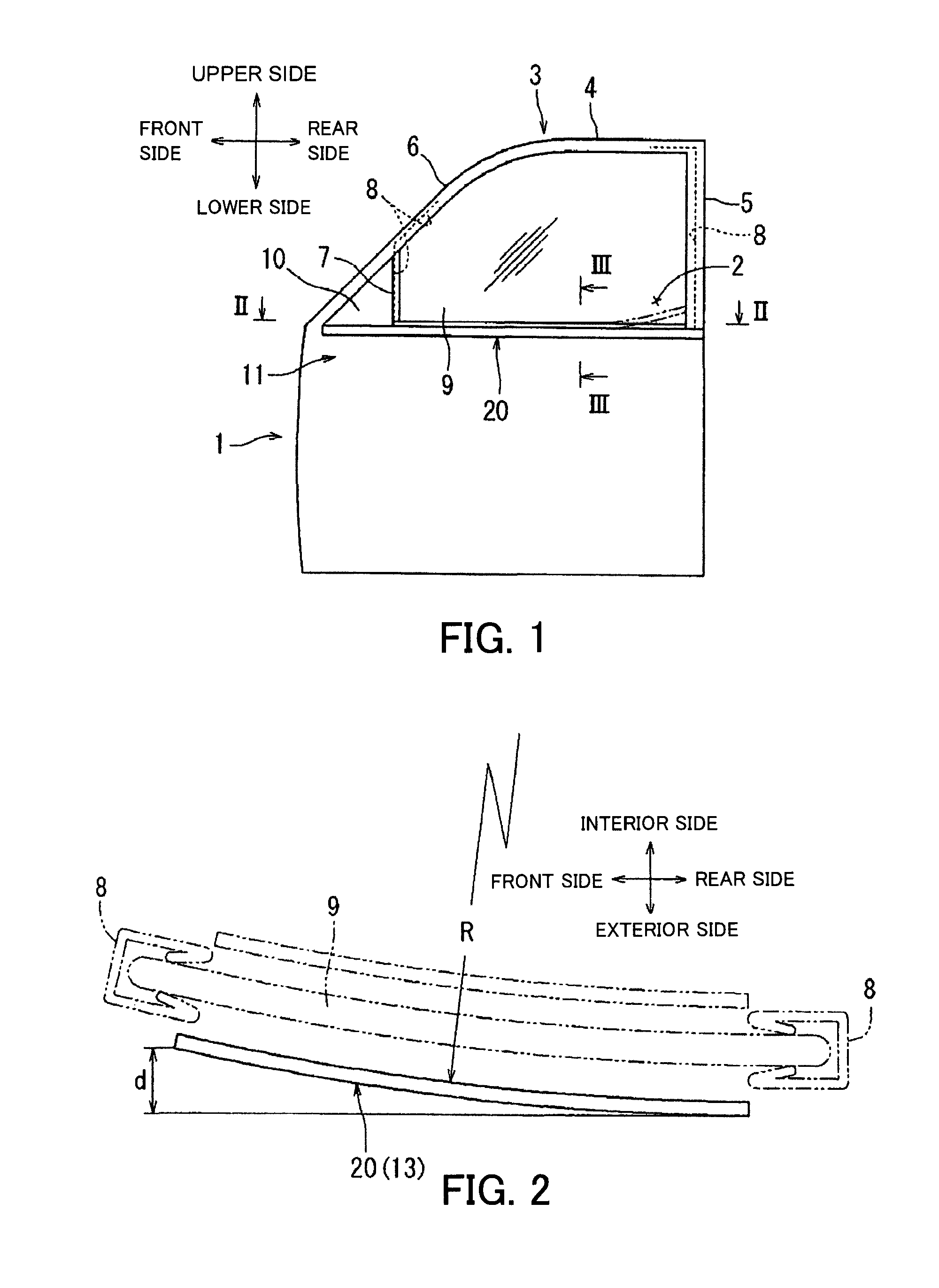
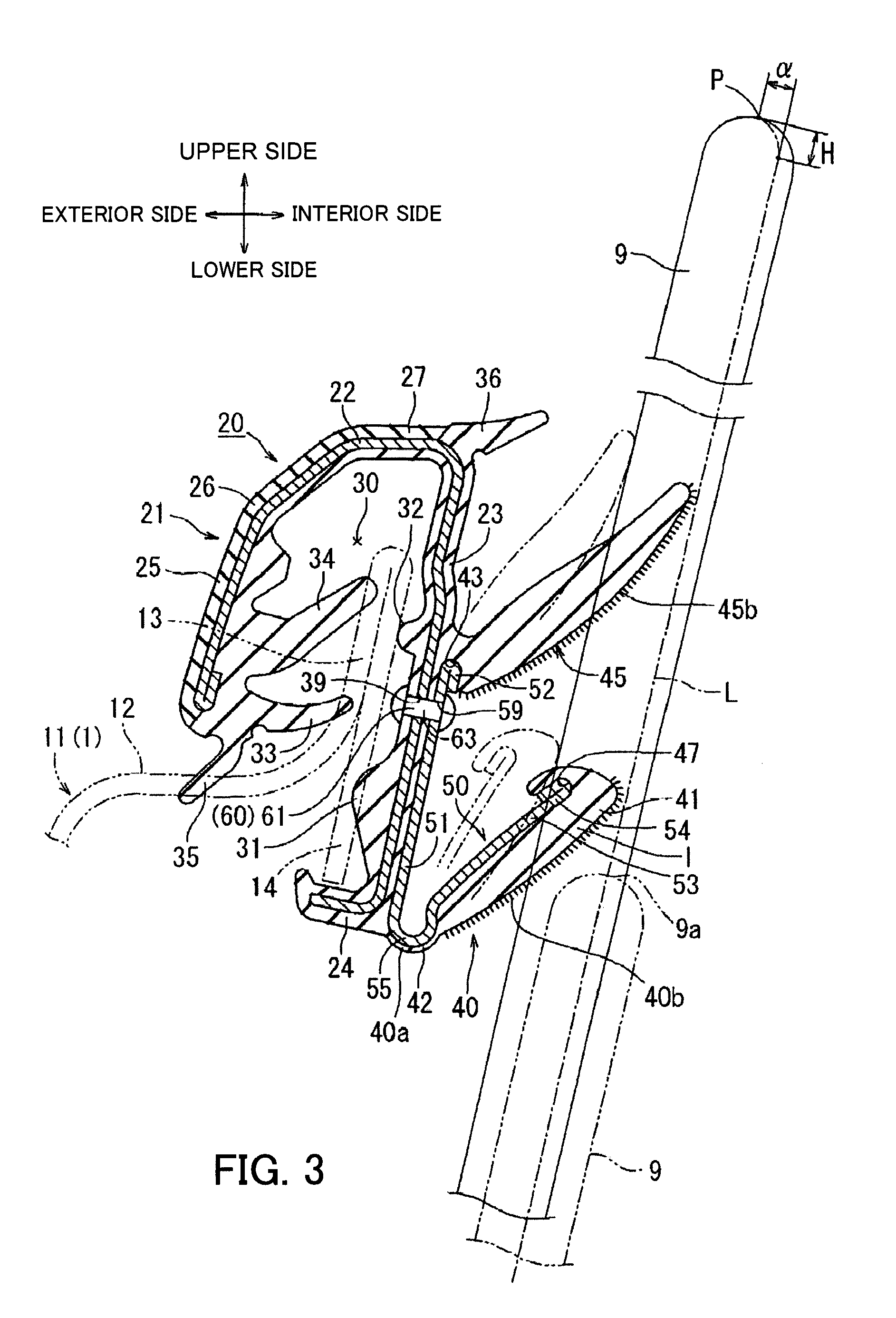
[0096]FIG. 1 is a side view showing the state in which a belt molding for vehicles according to a first embodiment of the present invention is mounted to a flange portion of a door outer panel as a mounting member. FIG. 2 is a cross-sectional view taken along the line II-II in FIG. 1. FIG. 3 is an enlarged cross-sectional view taken along the line III-III in FIG. 1. FIG. 4 is a front view showing an elastic repulsive member of the belt molding. FIG. 5 is a cross-sectional view taken along the line V-V in FIG. 4.
[0097]As shown in FIG. 1, the door outer panel 11 of the vehicle door 1 is provided with a window frame 3 integrally having an upper frame 4, a rear vertical frame 5, and an inclined front frame 6 constituting a window opening 2. In the window frame 3, a glass run channel 8 for guiding a window pane 9 for the open-close (up-and-down) movement i...
second embodiment
[0155]Next, a second embodiment according to the present invention will be explained with reference to FIG. 7.
[0156]FIG. 7 is a cross-sectional view (corresponding to the cross-sectional view taken along the line III-III in FIG. 1) showing the state in which a belt molding for vehicles according to a second embodiment of the present invention is mounted to a flange portion of a door outer panel as a mounting member.
[0157]As shown in FIG. 7, in this second embodiment, the attaching member 221 of the belt molding for vehicles 220 capable of being attached to the flange portion 13 as a mounting member is formed of a rigid polymer material harder than the seal lip. The first and second engage wall portions 223 and 225 and the connecting wall portion 227 of the attaching member 221, large and small projecting portions 231 and 232, and the engage portion 224 are formed into a long member by extruding a hard and rigid polymer material. The holding lips 233 and 234, the exterior seal lip 23...
third embodiment
[0160]Next, a third embodiment of the present invention will be explained with reference to FIGS. 8 to 10.
[0161]FIG. 8 is a cross-sectional view (corresponding to the cross-sectional view taken along the III-III in FIG. 1) showing the state in which a belt molding for vehicles according to a third embodiment of the present invention is mounted to a flange portion of a door outer panel as a mounting member, wherein the window pane is not illustrated since the structure is the same as in the first embodiment. FIG. 9 is a front view showing an elastic member of the belt molding, and FIG. 10 is a cross-sectional view taken along the line X-X in FIG. 9.
[0162]As shown in FIGS. 8 to 10, in this third embodiment, the attaching member 321 of the belt molding for vehicles 320 capable of being attached to the flange portion 13 as a mounting member is formed by extruding a soft elastic polymer material into a member having a generally inverted U-shape in cross-section, and includes, in the same...
PUM
 Abstract
Description
Claims
Application Information