Independent suture tensioning and snaring apparatus

a suture tensioning and snaring technology, applied in the field of apparatus and methods for anchoring soft tissue to bone, can solve problems such as bone creating additional problems

Active Publication Date: 2012-01-31
ARTHROCARE
View PDF358 Cites 34 Cited by
  • Summary
  • Abstract
  • Description
  • Claims
  • Application Information

AI Technical Summary

Benefits of technology

[0010]Respective first and second knobs may extend from the instrument housing while coupled to respective first and second ratchet wheels which are rotatably positioned within the housing. First and second ratchet wheels may include respective ratcheting teeth such that rotation of the first and second knobs by the user may in turn rotate ratchet wheels in a first direction while rotation in a second opposite direction is inhibited. One or both respective ratchet releases may be depressed or actuated by the user to release the ratcheting mechanism and thus allow for free rotation of the ratchet wheels in either the first or second direction. In this manner, one or both ratchet wheels may be released independently of one another to facilitate individual tensioning of one or both suture lengths via the ratchet wheels. Alternatively, both ratchet wheels may be simultaneously released by the simultaneous actuation of both ratchet releases.
[0011]In an exemplary use, when a first and second length of suture extending from their respective bone anchors deployed within the underlying bone are initially tensioned, the selector may be placed in a neutral position such that both first and second ratchet wheels are engaged by the selector and both wheels are simultaneously rotatable. Rotation of both first and second ratchet wheels may accordingly tension both lengths of suture simultaneously about their respective suture tracks for initially eliminating any slack from the suture lengths.
[0012]To disengage the first and second ratchet wheels from one another, the selector may be actuated, e.g., by depressing the selector in a first direction, to slide into a first position. In this first position, the second ratchet wheel may be disengaged and the first ratchet wheel may be engaged such that rotation of the knobs may in turn rotate only the first ratchet wheel to tension the first length of suture thereabout. With the second ratchet wheel disengaged from the knobs, the second ratchet wheel may remain stationary to maintain a constant tension level upon its suture length while the first ratchet wheel may be rotated to further tension or loosen its first length of suture as appropriate. Similarly, the selector may be actuated to be re-positioned into a second position where the first ratchet wheel is disengaged from the knobs and the second ratchet wheel is then engaged by the knobs to rotate for tensioning or loosening its respective suture length. Such individual tensioning of the sutures may provide for fine tuning and optimization of the soft tissue securement to the underlying bone.

Problems solved by technology

Even with the advent of knotless bone anchor designs, the ability to accurately and reliably apply tension to the sutures to approximate soft tissues to bone created additional problems.

Method used


Image

  • Independent suture tensioning and snaring apparatus
  • Independent suture tensioning and snaring apparatus
  • Independent suture tensioning and snaring apparatus

Examples


Embodiment Construction

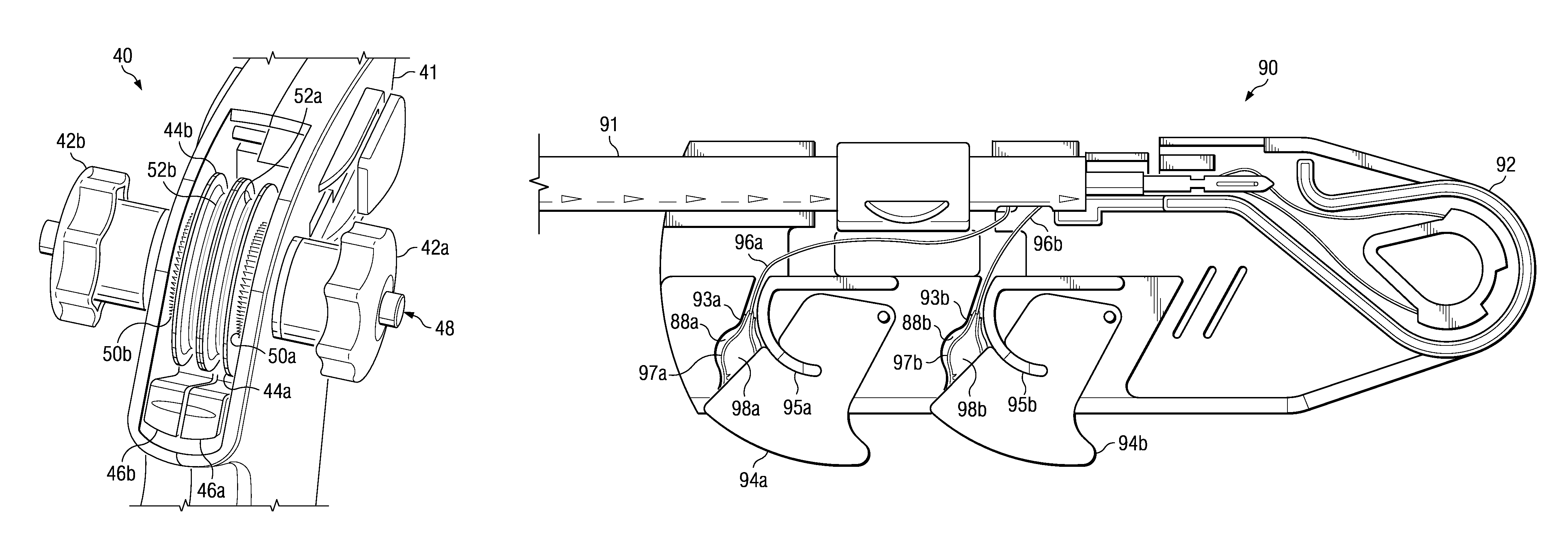
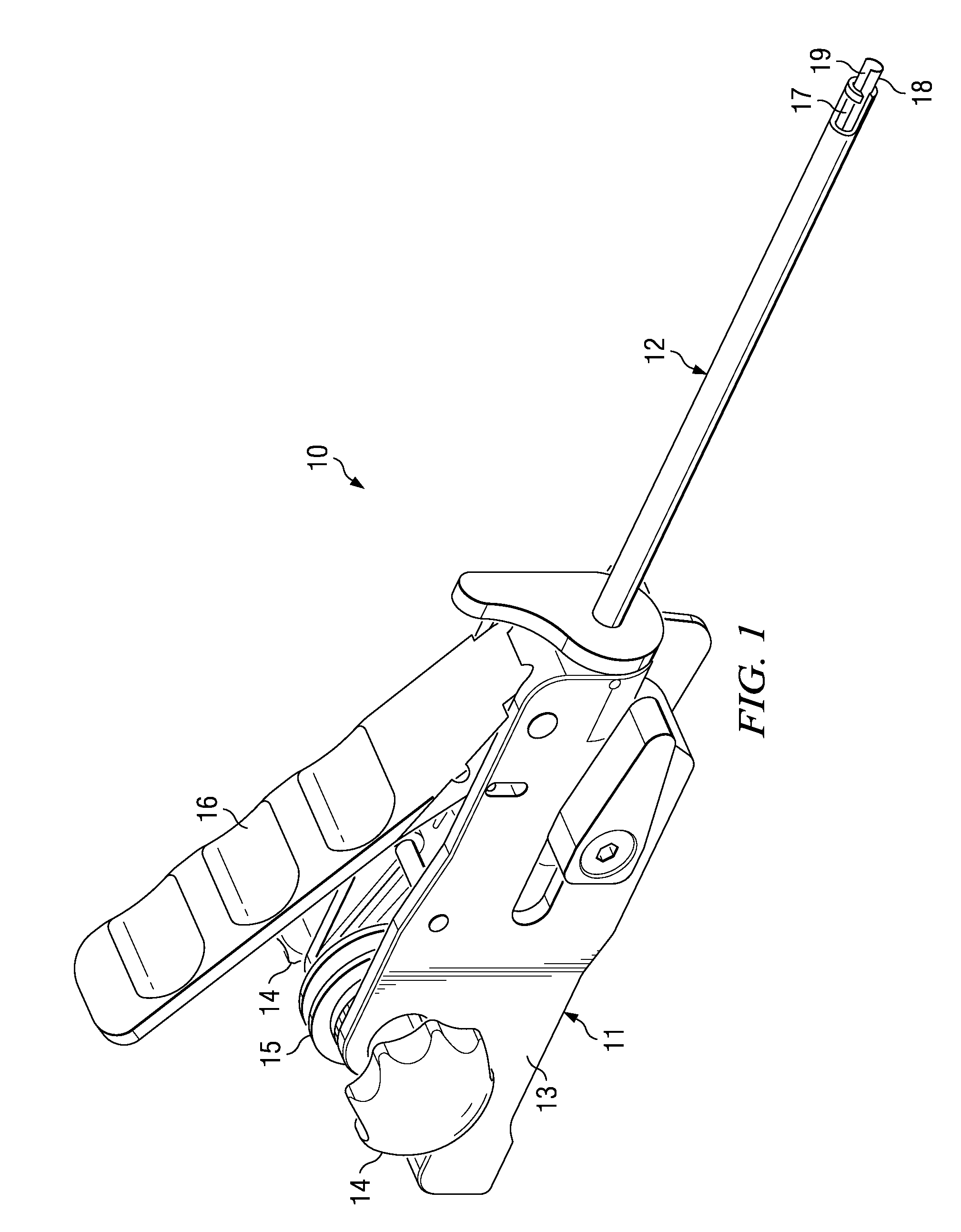
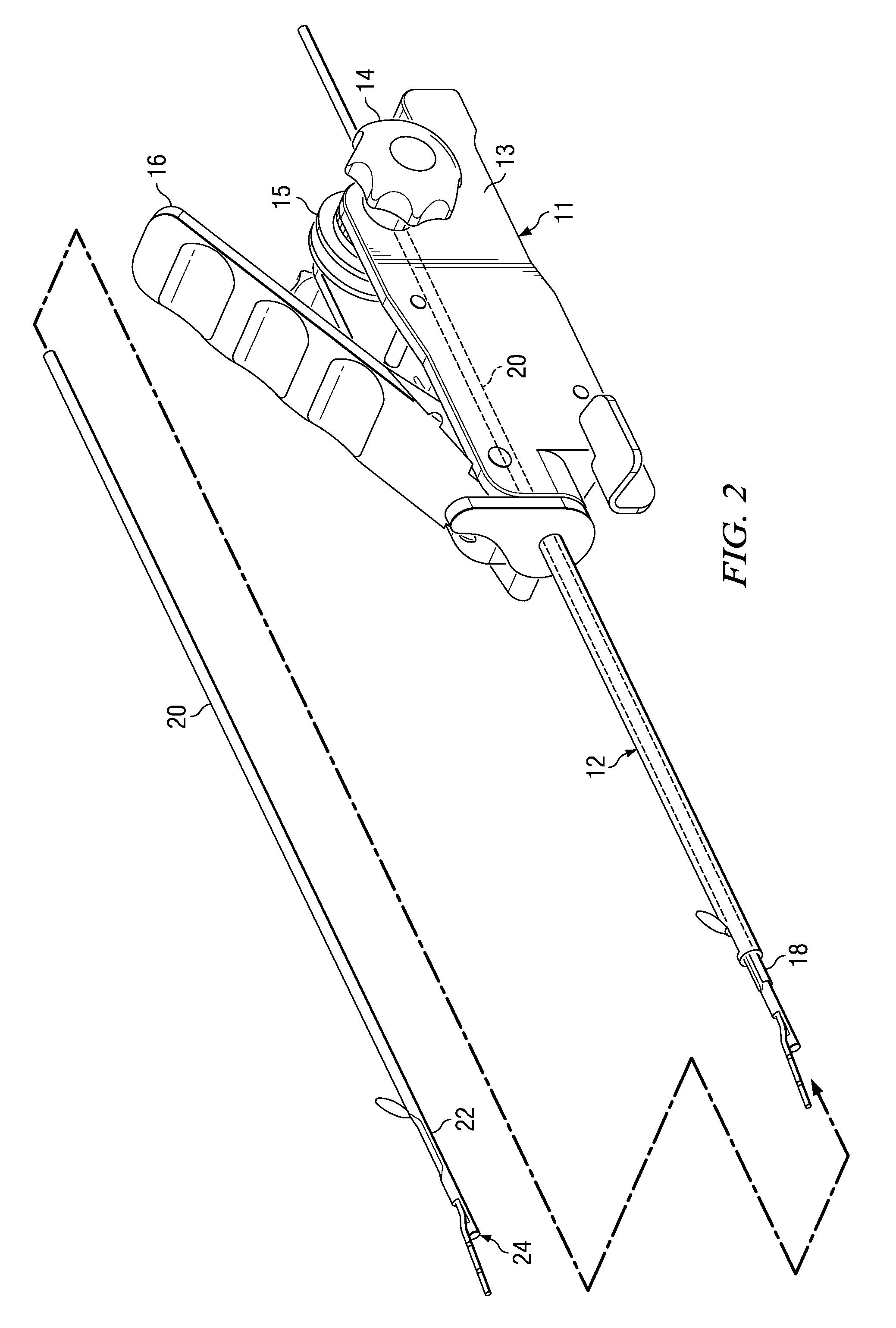
[0031]The independent suture tensioning mechanisms described herein may be utilized with any number of bone anchors as well as related insertion and deployment instruments. In repairing soft tissue with a bone anchoring instrument (such as reattaching a tendon of a torn rotator cuff), the bone anchoring instrument may be used to anchor the soft tissue to a region of bone. This may be accomplished generally by inserting at least one anchor into the underlying bone, locking the anchor into the bone, and subsequently tensioning one or more lengths of suture or wire stitched in the soft tissue between the anchor to affix the soft tissue. The lengths of suture or wire may be tensioned independently of one another and subsequently immobilized or secured and the anchoring instrument may be disassociated from the anchor leaving it behind in the bone. Such an anchoring instrument may eliminate the need to separately pass suture or wire or tying knots thus allowing the procedure to be perform...


PUM


Abstract

In repairing soft tissue with a bone anchoring instrument (such as reattaching a tendon of a torn rotator cuff), the bone anchoring instrument may be used to anchor the soft tissue to a region of bone. The anchors inserted into the underlying bone may have one or more lengths of suture or wire attached thereto which may be tensioned independently of one another to affix the soft tissue to the bone by having a selector mechanism selectively engage and disengage ratcheted tensioning wheels from one another. Suture loading mechanisms may be employed for passing suture lengths into and / or through the anchors prior to deployment into the bone where such mechanisms may employ suture snares which are configured to reconfigure from an expanded shape through which suture lengths may be easily passed to a low-profile shape which secures the suture lengths within the snare.

Description

CROSS-REFERENCE TO RELATED APPLICATIONS[0001]This application claims the benefit of U.S. Provisional Application No. 61 / 076,795 filed Jun. 30, 2008 and entitled “Independent Suture Tensioning and Snaring Apparatus”, the entirety of which is incorporated herein by reference in its entirety.FIELD OF THE INVENTION[0002]The present invention relates to apparatus and methods for anchoring soft tissue to bone. More particularly, the present invention relates to apparatus and methods for anchoring soft tissue to bone and selectively snaring, threading, and tensioning varying suture lengths from one or more bone anchors independently of one another through a single instrument.BACKGROUND OF THE INVENTION[0003]Prior to the development of knotless designs, bone anchor deployment instruments typically utilized anchors which had suture material either preloaded or incorporated eyelets through which a length of suture may be loaded prior to anchor introduction into the bone. The sequence of opera...

Claims


Application Information

Patent Timeline
Patent Type & Authority Patents(United States)
IPC IPC(8): A61B17/04A61B17/12
CPCA61B17/0401A61B17/0485A61B17/8869A61B17/04A61B17/06166A61B17/0482A61B2017/00296A61B2017/0409A61B2017/0496A61B2017/0464A61B2017/042A61B2017/0456A61B17/0469A61B2017/0414A61B17/00234A61B2017/0053
Inventor WHITE, GEORGE W.GREGOIRE, DAVIDALDRIDGE, DAVIDDOLENDO, EDWARD E.KARAPETIAN, EMILGORDON, NORMAN S.NGUYEN, TRI
Owner ARTHROCARE
Why Eureka
Try Eureka