Desk top panel and a desk with the same

a desk and top panel technology, applied in the direction of lecterns, furniture parts, dismountable cabinets, etc., can solve the problems of reducing the effective use of the top board, affecting the work efficiency of the desk, so as to achieve the effect of easy removal or opening, and reducing the effective working area

Inactive Publication Date: 2012-02-07
OKAMURA CORP
View PDF25 Cites 30 Cited by
  • Summary
  • Abstract
  • Description
  • Claims
  • Application Information

AI Technical Summary

Benefits of technology

[0011]In view of the disadvantages, it is an object of the invention to provide a desk top panel and a desk with the desk top panel, the desk being normally partitioned by a desk top panel to protect privacy, lower part of the desk top panel being opened, if necessary, to enable face-to-face persons to talk with each other and to give / receive documents, a wire cover being easily removed or opened.
[0012]It is another object of the invention to provide a desk top panel having a wire storage space under a desk top panel without reducing effective working area on a top board of the desk.

Problems solved by technology

In JP3-98634U, JP2000-287758A and JP2006-149554A, when the desk top panel is mounted, the wire cover may be obstructed from opening / closing and taking on / off, and wiring will become more difficult.
When the wire opening is along the desk top panel, a working space is reduced, so that the top board will be less effective in use.

Method used


Image

  • Desk top panel and a desk with the same
  • Desk top panel and a desk with the same
  • Desk top panel and a desk with the same

Examples


first embodiment

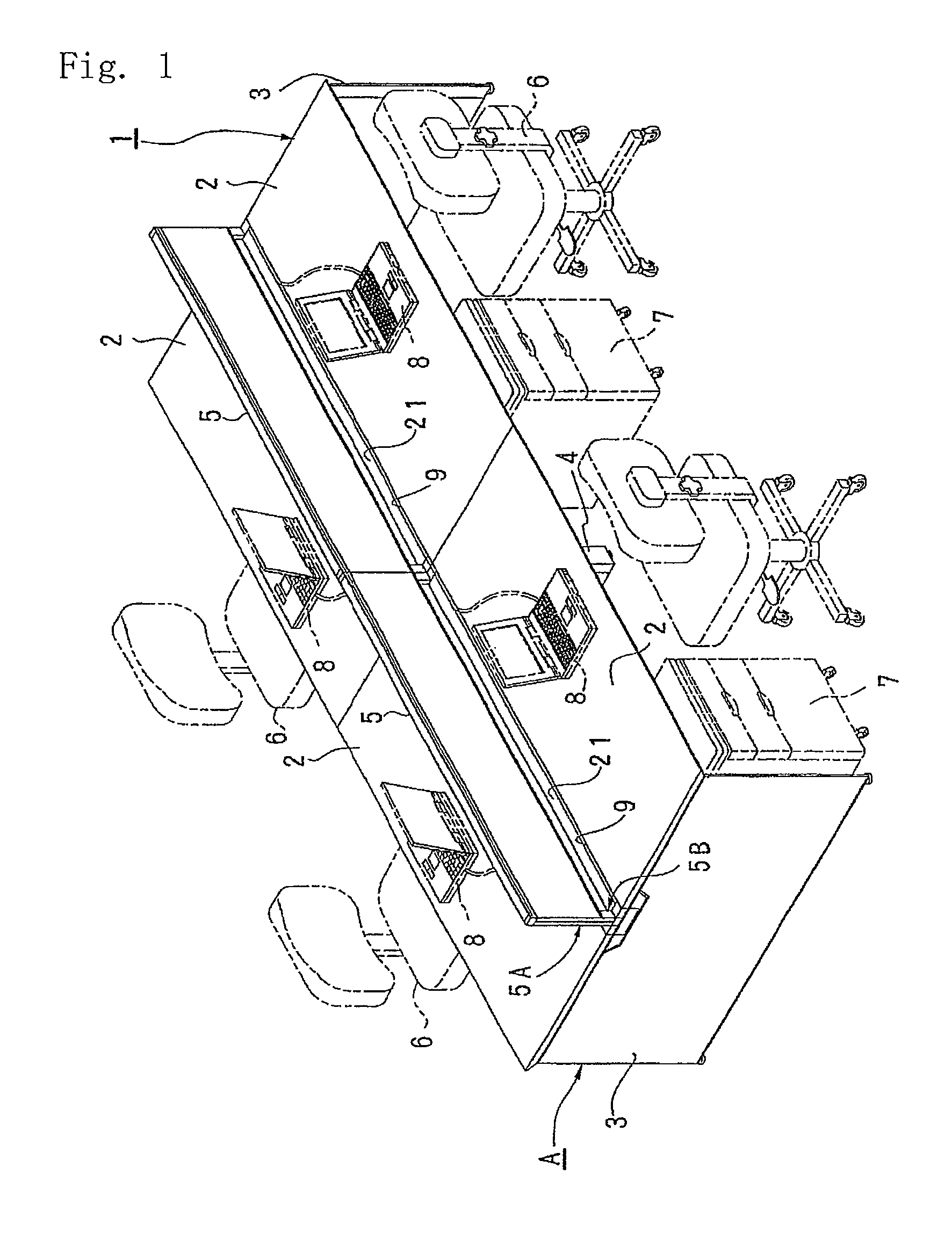
[0025]FIGS. 1-3 show the invention.

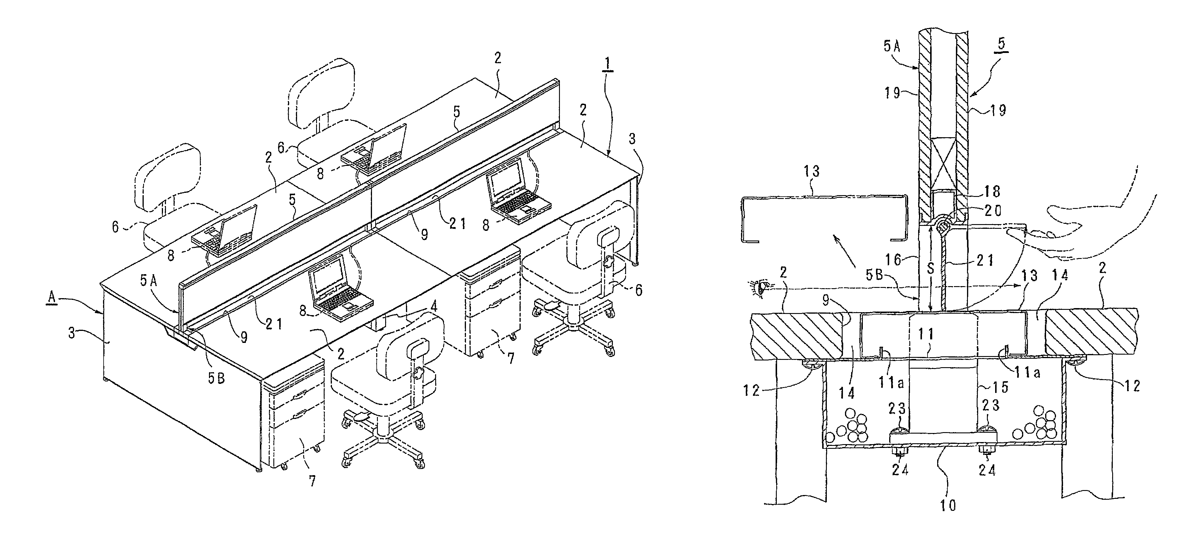
[0026]In FIG. 1, a desk 1 comprises four top boards 2 in which the two boards face each other, while the two boards are arranged side by side. The top boards 2 are supported by a top support A comprising a pair of side panels 3,3; intermediate legs 4 therebetween; and a beam (not shown) for connecting the intermediate legs 4. The desk 1 is a face-to-face type.

[0027]Between the top boards 2 and 2, there is provided a desk top panel 5 for blocking front visibility of sitting persons on a chair 6, shown by two-dot-dash lines in front of each of the top boards 2.

[0028]Under each of the top boards 2, there is a side wagon 7 as shown by two-dot-dash lines beside the chair 6. On the upper surface of the top board 2, there are a notebook computer 8 in two-dot-dash lines and other electric appliance (not shown). A power source code and a connecting cable pass through an elongate opening 9 between the top boards 2 and 2 under the desk top panel 5 and is stor...

second embodiment

[0043]FIGS. 4-6 show the invention. The same numerals are allotted to the same members as the foregoing embodiment, and detailed description thereof is omitted.

[0044]In FIG. 4, an engagement groove 26 is formed at the lower part of a lower horizontal frame 25. In FIG. 6, a plurality of shaft-support blocks 27 engage in the engagement groove 26 at regular intervals. The shaft-support block 27 has a lower semicircular section. In the lower part and sides of the outer circumference of the semicircular section, positioning elastic engagement projections 28 are provided, and a shaft 30 projects from the sides of the shaft-support block 27 at the center of the semicircular section, and the closing member 29 turns with the shaft 30. The shaft 30 may be integrally formed with the shaft-support block 27.

[0045]A closing member 29 is molded of synthetic resin and has a pair of arc-like elastically deformable shaft-holding portions 29a,29a at the upper end. In the middle of the upper end of the...

third embodiment

[0051]the invention is shown in FIGS. 7 and 8.

[0052]In the embodiment, a pair of shaft support blocks 33 is fixed to the sides of the lower end of a lower horizontal frame 32, and each end of a shaft 35 around which the closing member 34 turns is pressed and fitted in the shaft support block 33. An upper flat surface 35a is formed on the shaft 35 and is corresponding in shape to an engagement hole 36 in the shaft-support block 31.

[0053]The closing member 34 comprises a pair of elastically deformable shaft-holding portions 34a,34a similar to the second embodiment. The distance between the shaft-holding portions 34a and 34a is smaller than an external diameter of the shaft 35. In FIG. 8A, when the closing member 34 is in the closed position, the shaft-holding portions 34a,34a expands at largest, and the side edge of the flat surface 35a of the shaft 35 is held by the shaft-holding portions 34a,34a stably in the closed position. In FIG. 8C from FIG. 8B, when the closing member 34 turns...


PUM


Abstract

Provided is a desk top panel, which normally protects privacy in a complete shielding form, permits facing persons to converse and documents and the like to be passed and received by opening a lower space of the desk top panel as needed, and permits a wiring cover to be easily attached / removed or opened / closed. A desk having such desk top panel attached thereon is also provided. A desk top panel is attached to the rear portion of a top board of a desk to stand, for blocking the visual fields of sitting persons. The desk top panel is provided with a panel-like main body; a pair of right and left attaching sections, which vertically extend downward from the both lower end portions of the main body by having the lower end sections attached to the top board or a top board supporting body of the desk; and a closing plate, attached to the lower end of the main body to be opened / closed, so that a space formed between the main body and the upper surface of the top board of the desk can be opened / closed when both the attaching sections are attached to the desk.

Description

CROSS REFERENCE TO RELATED APPLICATIONS[0001]The present application is a 35 U.S.C. §371 National Phase conversion of PCT / JP2007 / 071511, filed Nov. 6, 2007, which claims benefit of Japanese Application No. 2006-304225, filed Nov. 9, 2006 and Japanese Application No. 2006-304226, filed Nov. 9, 2006, the disclosures of which are incorporated herein by reference. The PCT International Application was published in the Japanese language.BACKGROUND OF THE INVENTION[0002]The present invention relates to a desk top panel on the upper surface of a top board of a desk to block visibility of a person and a desk with the desk top panel.[0003]Such a desk top panel is a perfectly-partitioned type as disclosed in JP2004-313471A. There is also a desk top panel where only upper part is partitioned and lower part comprises only posts for supporting the upper part to create openings between the posts.[0004]JP2006-6771A discloses a wire storage space under a desk top panel.[0005]Furthermore, JP3-98634U...

Claims


Application Information

Patent Timeline
Patent Type & Authority Patents(United States)
IPC IPC(8): A47B37/00
CPCA47B21/00A47B21/06E04B2/7422E04B2002/7483E04B2002/7488A47B2200/12
Inventor KITADA, KAZUHIKONOZAKI, OSAMU
Owner OKAMURA CORP
Why Eureka
Try Eureka