Pig tail spring exhaust hanger

a technology of exhaust hangers and springs, which is applied in the field of hangers, can solve the problems of complex and multiplicity of components, degradation of resilient bodies over time, and achieve the effect of constrained

Inactive Publication Date: 2012-02-07
GM GLOBAL TECH OPERATIONS LLC
View PDF15 Cites 4 Cited by
  • Summary
  • Abstract
  • Description
  • Claims
  • Application Information

AI Technical Summary

Benefits of technology

[0008]The pig tail spring exhaust hanger includes a metal pig tail coil having at one end an integral upper arm and at the opposite end an integral lower arm. The upper arm is mounted to the vehicle underbody, and the lower arm is connected to the exhaust pipe or other exhaust component, such as for example the muffler or catalytic converter. Preferably, the orientation of the upper and lower arms is substantially vertical and the orientation of the central axis of the pig tail coil is substantially horizontal. By providing a generally vertical orientation of the upper and lower arms and a generally horizontal orientation of the central axis of the pig tail coil, the pig tail spring exhaust hanger provides a pair of radial flexing (or working) moments of the pig tail coil, one moment at each of the upper and lower arms. As such, the suspended weight of the exhaust system acts radially with respect to the pig tail coil, rather than axially, as used in current conventional exhaust spring hangers. By supporting the exhaust system load radially, rather than the axially, the exhaust system can be more effectively constrained than is possible with conventional axially loaded exhaust spring hangers, while simultaneously eliminating traditional rubber isolator bodies, which can degrade over time.
[0009]Accordingly, it is an object of the present invention to provide a pig tail spring exhaust hanger which is free of the deficiencies of conventional exhaust hanger assemblies.

Problems solved by technology

While this form of exhaust hanger serves its purpose well, it suffers from degradation over time of the resilient body (typically rubber or rubber-like material), as well as the cost associated with the complexity and multiplicity of the components, as well as the assembly, of a typical exhaust hanger assembly.

Method used


Image

  • Pig tail spring exhaust hanger
  • Pig tail spring exhaust hanger
  • Pig tail spring exhaust hanger

Examples


Embodiment Construction

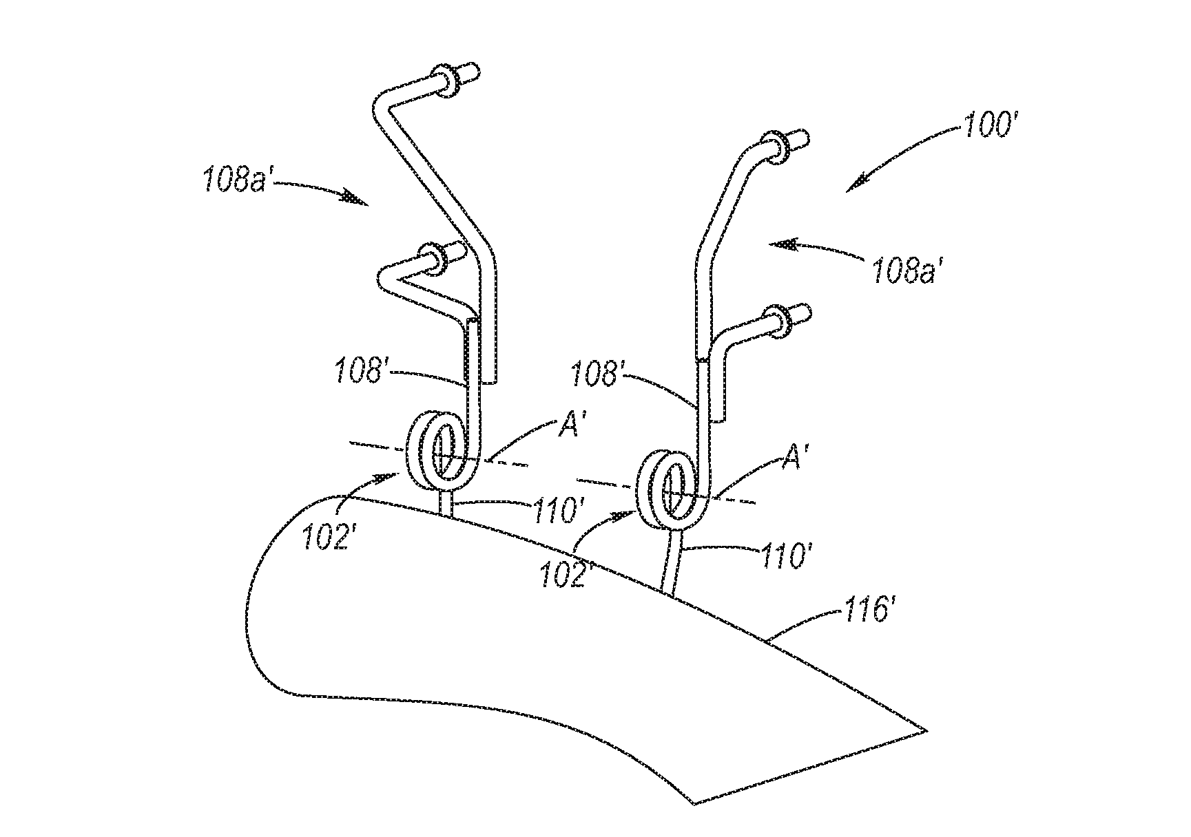
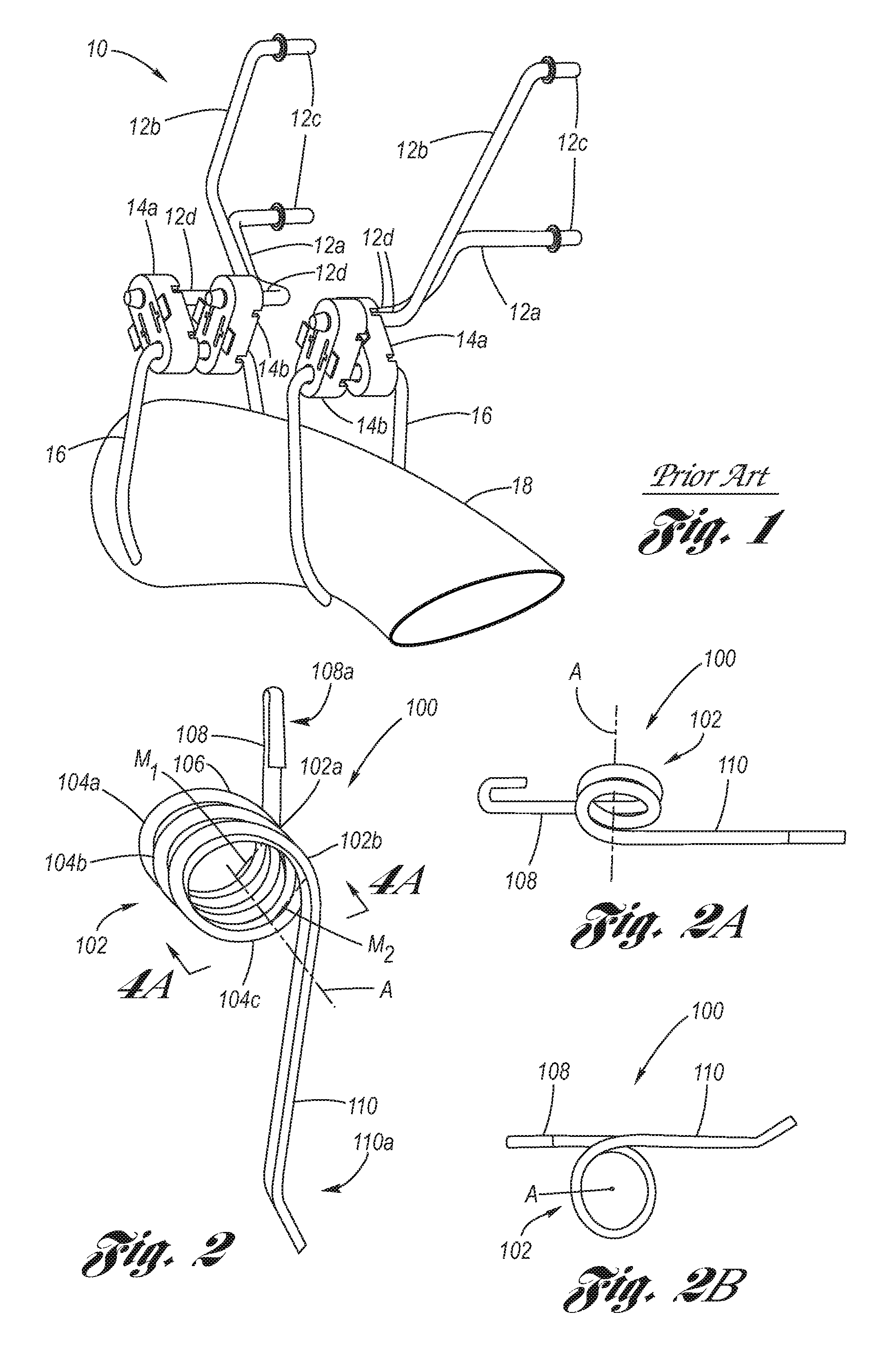
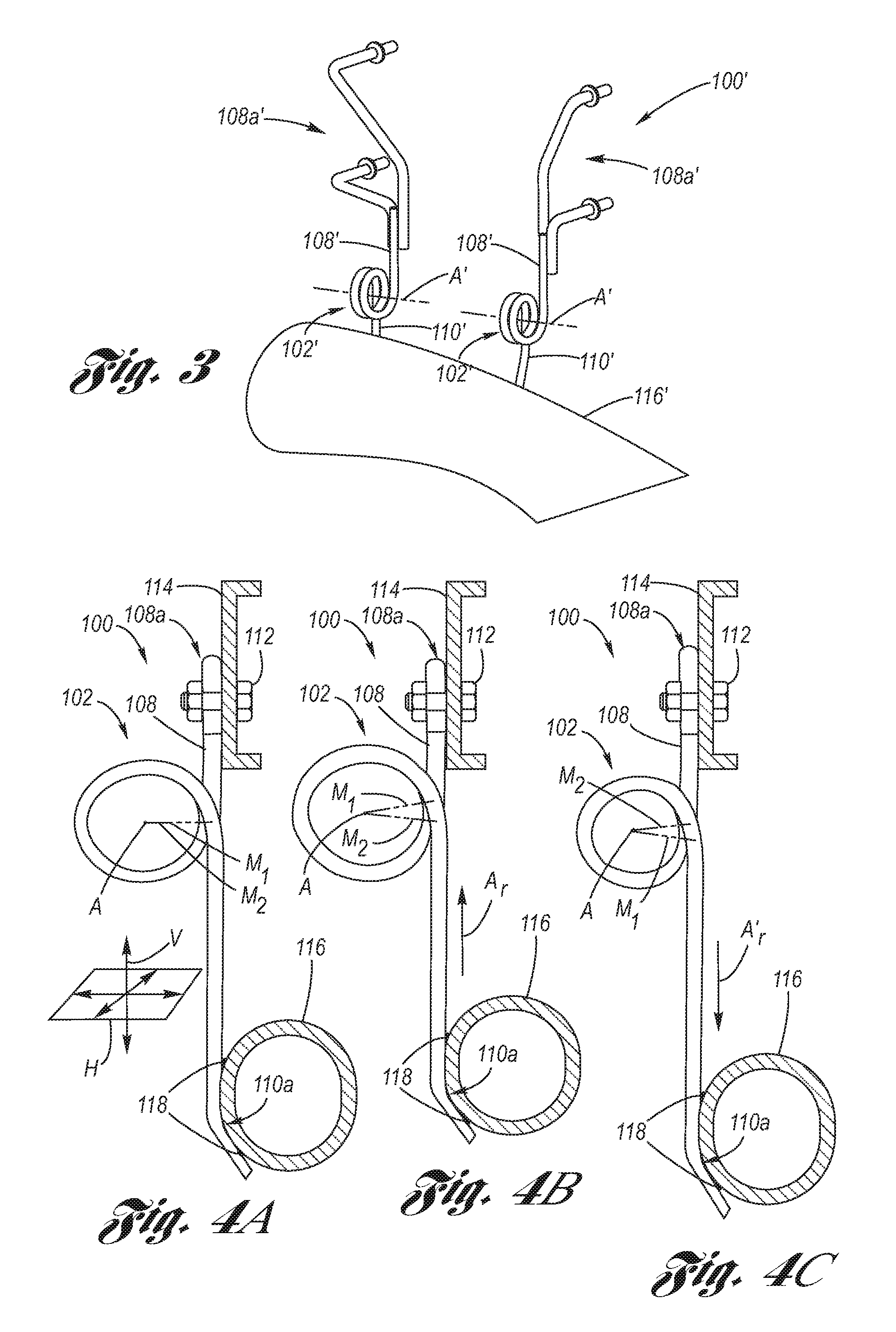
[0019]Referring now to the Drawing, FIGS. 2 through 4C depict examples of a pig tail spring exhaust hanger 100, 100′ according to the present invention.

[0020]Referring firstly to FIG. 2, a pig tail spring exhaust hanger 100 is depicted. The pig tail spring exhaust hanger 100 includes a pig tail coil 102 composed of at least one loop, wherein first, second and third loops 104a, 104b, 104c are shown merely by way of example. The pig tail coil 102 is formed of a metallic rod 106, as for example a spring steel rod. The rod 106 composing the pig tail coil 102 extends continuously at each end thereof, forming an upper arm 108 at a first end 102a of the pig tail coil and a lower arm 110 at the opposite, second end 102b of the pig tail coil, whereby, preferably, the pig tail exhaust hanger 100 is formed of a single piece construction.

[0021]The upper arm 108 extends tangentially off from the first end 102a of the pig tail coil 102, shown at the first loop 104a in FIG. 2, and radially with re...


PUM


Abstract

A pig tail spring exhaust hanger includes a pig tail coil having at one end an upper arm and at the other end a lower arm. The upper arm is mounted to the vehicle underbody, and the lower arm is connected to the exhaust system, wherein the orientation of the upper and lower arms is substantially vertical and the orientation of the central axis of the pig tail coil is substantially horizontal. This arrangement provides a moment at each of the upper and lower arms which act to suspended weight of the exhaust system radially with respect to the pig tail coil.

Description

TECHNICAL FIELD[0001]The present invention relates to hangers utilized for hanging exhaust components of a motor vehicle with respect to the underbody thereof.BACKGROUND OF THE INVENTION[0002]Motor vehicles utilizing internal combustion engines pipe the exhaust under the vehicle, wherein the exhaust system is flexibly suspended from the vehicle underbody by one or more exhaust hanger assemblies. A typical exhaust hanger assembly uses flexible elements having low stiffness to support the exhaust pipe in combination with stiffer elements having higher resonant frequencies for attaching the exhaust hanger assembly to the underbody of the vehicle. Together, these elements serve to impede the transmission of noise and vibration from the exhaust system to the floor of the passenger compartment. In addition, the exhaust hanger assembly also prevents the transmission of heat from the exhaust system to the vehicle underbody.[0003]As described in U.S. Pat. No. 5,673,877, a typical prior art e...

Claims


Application Information

Patent Timeline
Patent Type & Authority Patents(United States)
IPC IPC(8): E21F17/02F16L3/00
CPCF16L3/205
Inventor KERCHNER, DOUGLAS M.
Owner GM GLOBAL TECH OPERATIONS LLC
Why Eureka
Try Eureka