
Display housing

Inactive Publication Date: 2012-02-07
PORCELAIN PROMOTIONS
View PDF17 Cites 23 Cited by
  • Summary
  • Abstract
  • Description
  • Claims
  • Application Information

AI Technical Summary

Benefits of technology

[0025]The base panel, the top panel, the bottom panel, the first side panel and the second side panel include a top elastic polymer strip, a bottom elastic polymer strip, a first elastic polymer strip and a second elastic polymer strip respectively, for compression between the cabinet and the face plate. The top elastic polymer strip, the bottom elastic polymer strip, the first elastic polymer strip and the second elastic polymer strip provide an expansion force between the cabinet and the face plate for maintaining engagement of the coupling between the pyramid body and the cabinet.

Problems solved by technology

Providing information and advertising to the general public in public places such as bus and train stations, public meeting places, and public rest rooms and the like presents security and vandalism problems for the purveyor of such information.
Deliberate defacing and destruction of the equipment used to provide such information by vandals has challenged the designers and manufacturers to produce vandal proof, or at least vandal resistant equipment.
Although the devices of the prior art have addressed the problems of defacing and destruction, none have completely solved these problems associated with the malicious behavior of vandals.
As a significant improvement, the construction of the within cabinet effectively masks the presence of the structural features which contribute to the door compound movement, whereas this is not the case with prior art cabinet doors and, as a result, such omission in an obvious way, detracts from the effectiveness of the security intended to be gained by the compound door movement.
Advantageously, the shell-like forward surface is softly rounded to an extent that it is practically impossible to obtain a handhold on the top or sides of the outer housing, whereby a vandal will be pre-vented from grabbing the dispenser and pulling it off the wall.
Although the devices of the prior art have partially solved the problems associated with malicious vandalism of devices in public places, none has totally solved the problem.

Method used


Image

  • Display housing
  • Display housing
  • Display housing

Examples


Embodiment Construction

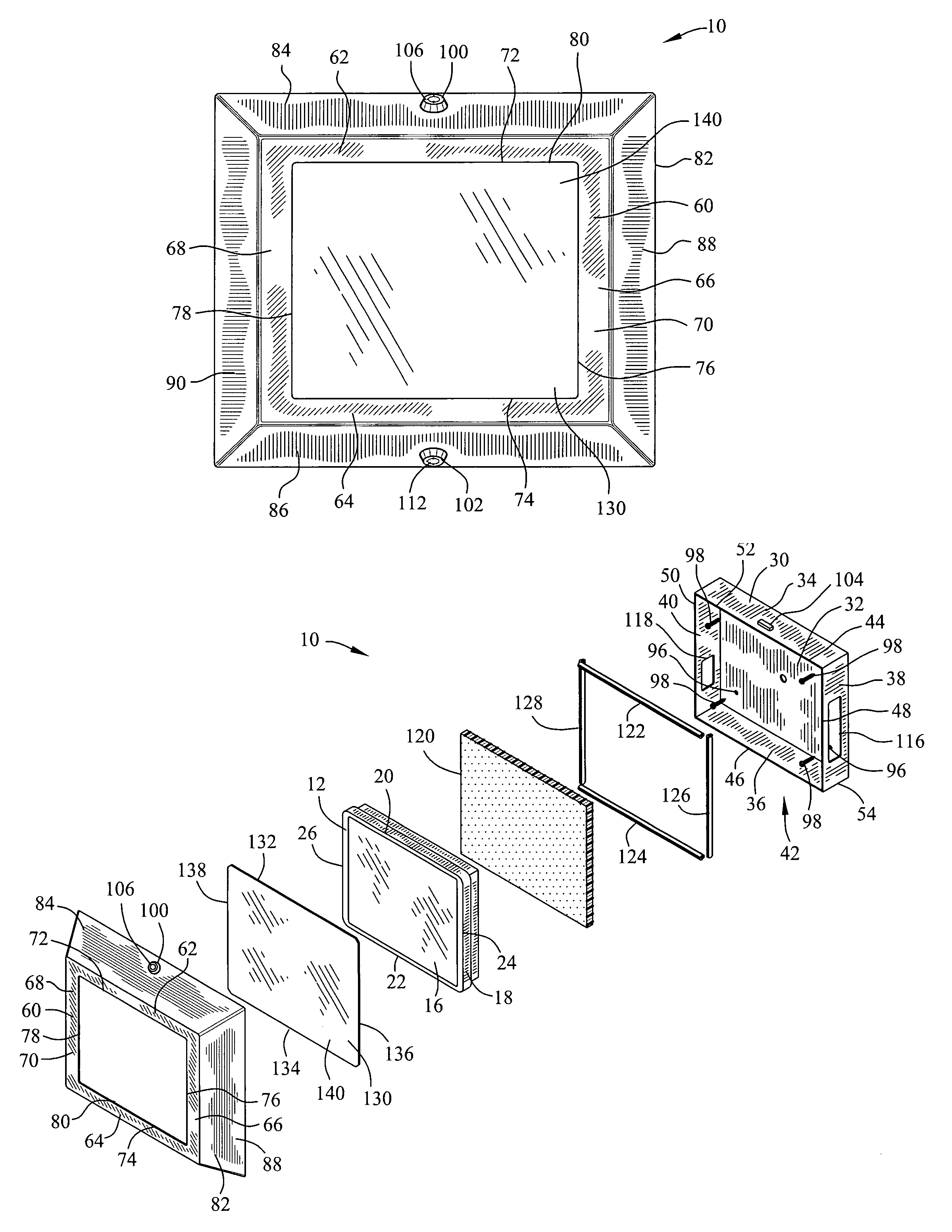
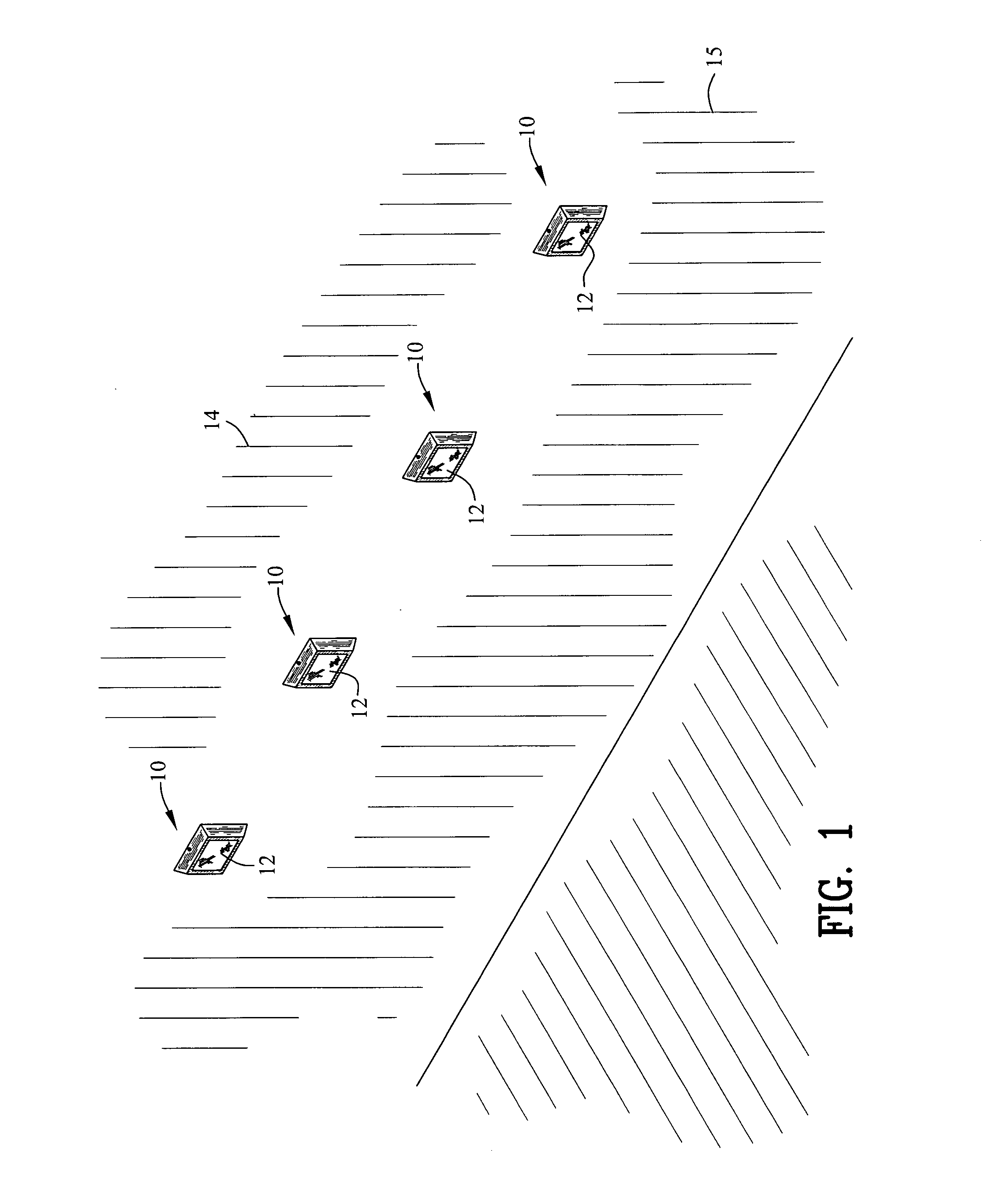
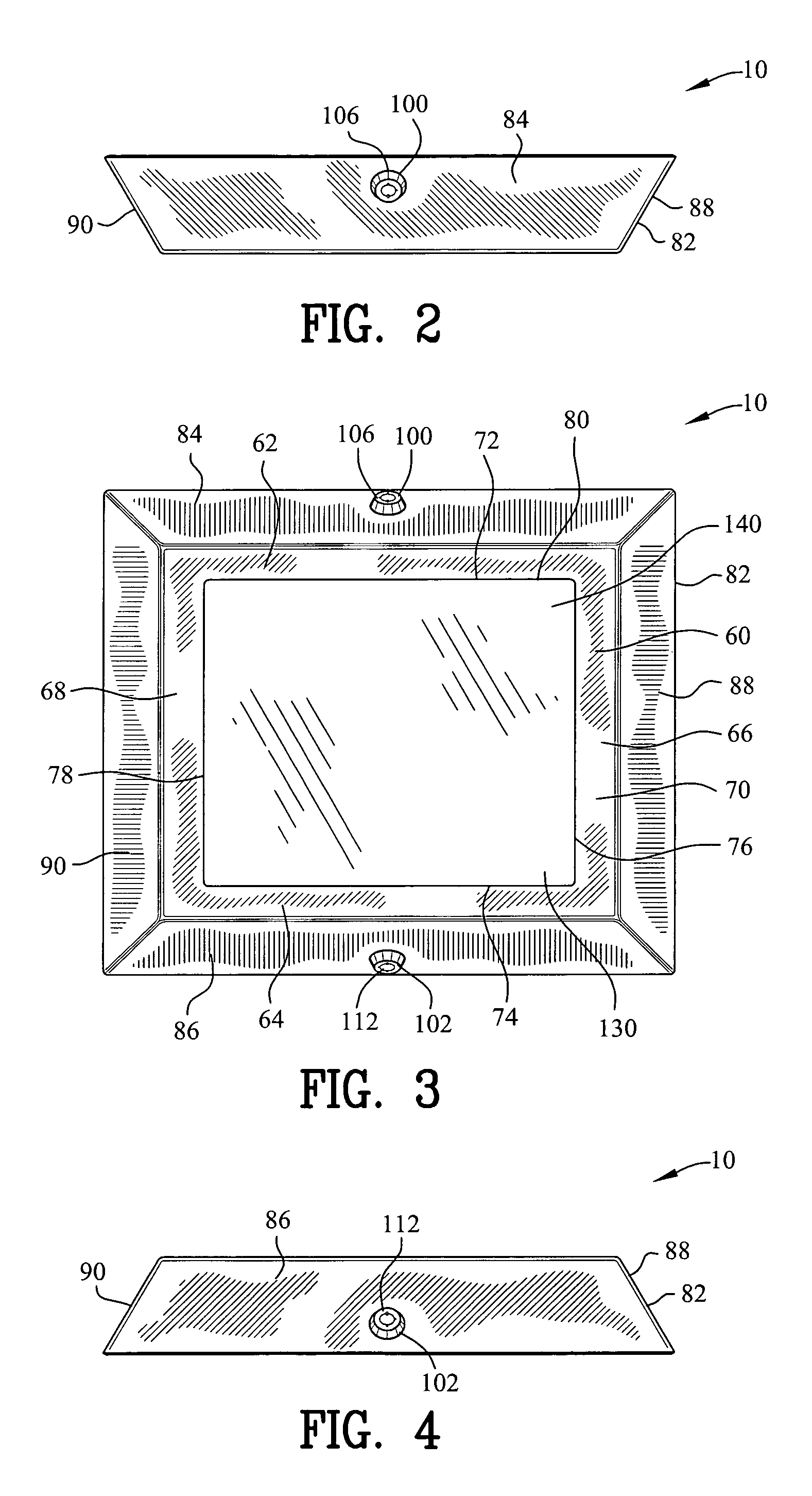
[0048]FIGS. 1-18 are various views of an enclosure 10 for housing a visual display device 12 adjacent to a surface 14. The visual display device 12 includes a monitor 16 for displaying a viewable image. He monitor 16 may include but is not limited to a thin film transistor liquid crystal display. The monitor 16 is electrically coupled to a memory device 18. The memory device 18 provides electronic signals to the monitor 16. The memory device 18 may include but is not limited to, optical discs, magnetic storage, or static memory devices. The memory device 18 is coupled to a central processing unit for controlling the iconic signals between the monitor 16 and the memory device 18. The monitor has a first edge 20, a second edge 22, a third edge 24 and a fourth edge 26 for defining a display area 28.

[0049]The visual display device 12 provides information regarding advertisements, promotional information, and / or other data. The enclosure 10 may be positioned on a vertical surface, a hori...


PUM


Abstract

An enclosure device is disclosed for housing a visual display device adjacent to a surface. The enclosure comprises a cabinet defining a cabinet chamber. A face plate defines a continuous frame. A pyramid body defines a cover chamber. The cabinet chamber receives the visual display device. The face plate compresses against the cabinet, for simultaneously positioning the face plate over the visual display device and positioning the pyramid body adjacent to the wall.

Description

CROSS-REFERENCE TO RELATED APPLICATIONS[0001]This application claims benefit of U.S. Patent Provisional application Ser. No. 61 / 130,477 filed May 31, 2008. All subject matter set forth in provisional application Ser. No. 61 / 130,477 is hereby incorporated by reference into the present application as if fully set forth herein.BACKGROUND OF THE INVENTION[0002]1. Field of the Invention[0003]This invention relates to enclosures and more particularly to an enclosure device for housing a visual display device.[0004]2. Background of the Invention[0005]Providing information and advertising to the general public in public places such as bus and train stations, public meeting places, and public rest rooms and the like presents security and vandalism problems for the purveyor of such information. Deliberate defacing and destruction of the equipment used to provide such information by vandals has challenged the designers and manufacturers to produce vandal proof, or at least vandal resistant equ...

Claims


Application Information

Patent Timeline
IPC IPC(8): A47F5/08
CPCG09F19/22G09F27/00G09F2007/1843
Inventor DIDIER, DAMONHURST, JOEMILLER, MATTHEWBOURASSA, BOBSEAL, RICK
Owner PORCELAIN PROMOTIONS
Learn More