Supercharge Your Innovation With Domain-Expert AI Agents!

Wind turbine

a wind turbine and blade technology, applied in the direction of rotors, electric generator control, machines/engines, etc., can solve the problems of increasing the cost of wind turbines, increasing the length and width of blades, and being stronger and more expensiv

Inactive Publication Date: 2012-02-07
BARBER GERALD L
View PDF68 Cites 29 Cited by
  • Summary
  • Abstract
  • Description
  • Claims
  • Application Information

AI Technical Summary

Benefits of technology

This design enables the use of lighter materials, reduces stress on blades, and maintains a consistent generator load by adjusting sailwing shape in response to wind conditions, enhancing energy capture and reducing directional changes.

Problems solved by technology

The blades of the conventional wind turbines are very large and made of expensive rigid material and are constructed to have the blades extend radially from a central hub, with no extra support at the outer tips of the blades.
Since the outer portions of the blades move at a very high velocity and are engaged by strong winds, the larger the blades the stronger they must be and the more expensive they become.
Thus, there is a practical limit as to the length and width of the blades because of the expense of stronger materials for larger blades.
However, the relative speed of the wind on a turbine wheel is greater near the outer portions of the blades of the turbine wheel in comparison with the inner portions of the blades, and the above noted patents do not teach adjustments for changing the pitch or twist of the cloth blades in a turbine wheel for compensating for different wind loads on different parts of the blades.
Others may increase the load applied by the electrical generator that is driven by the wind turbine.

Method used


Image

  • Wind turbine
  • Wind turbine
  • Wind turbine

Examples


Embodiment Construction

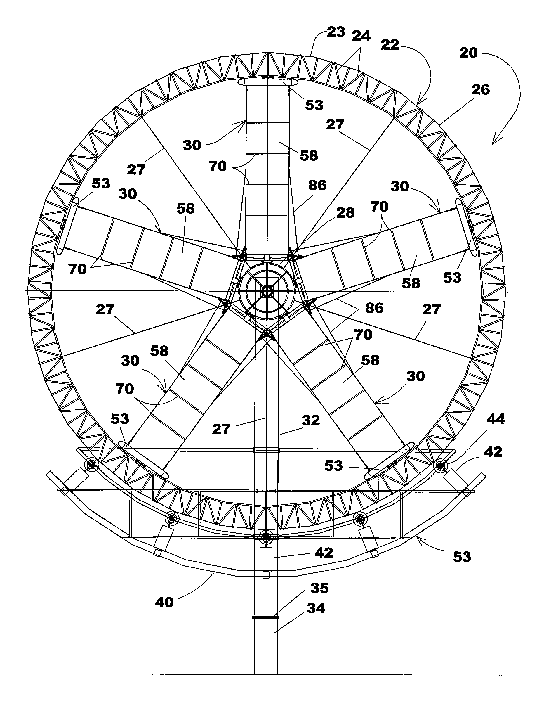
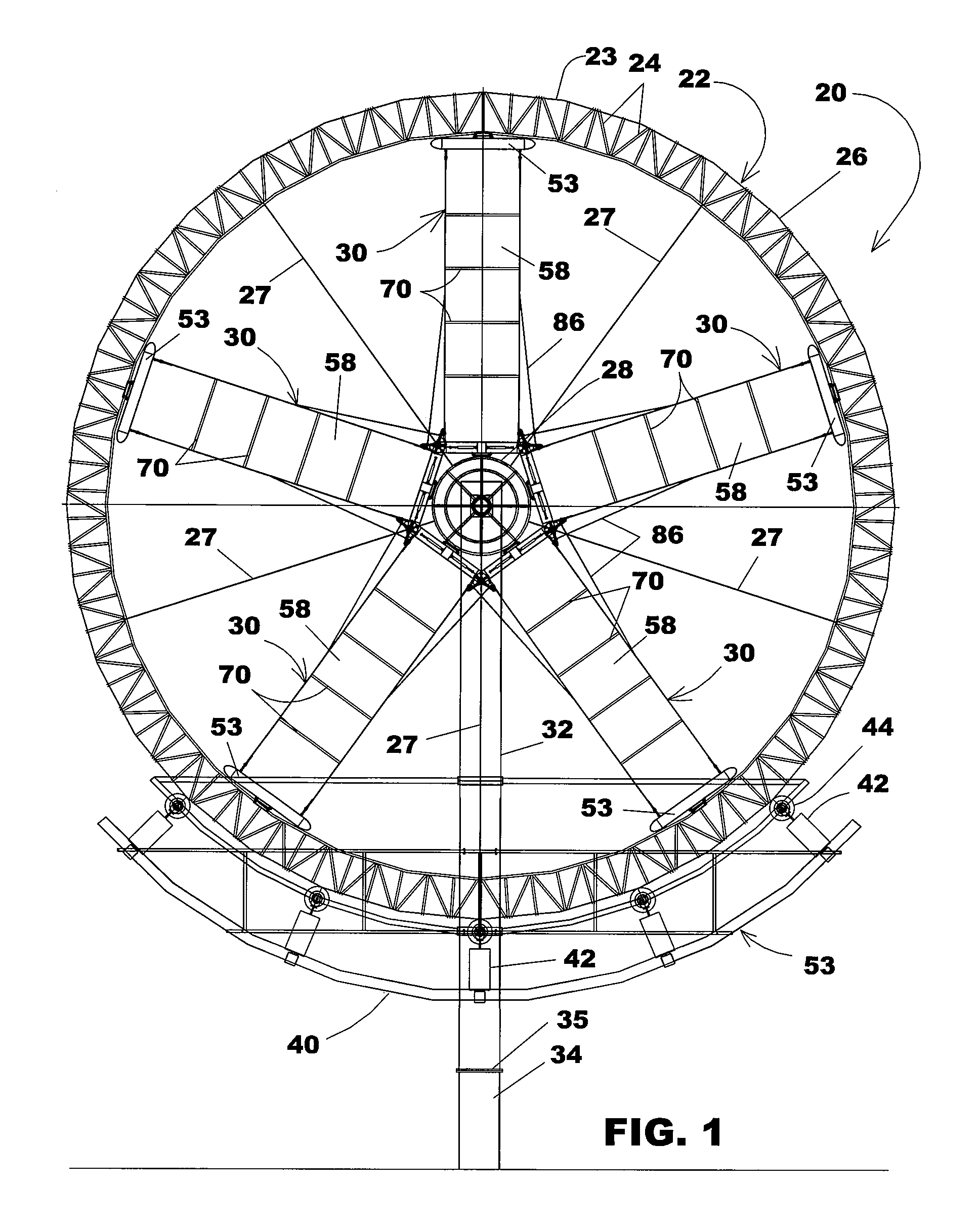
[0031]Referring now in more detail to the drawings in which like numerals indicate like parts throughout the several views, FIG. 1 shows a wind turbine 20 that includes a turbine wheel 22 having an outer perimeter 23 formed by a series of angled braces 24 and a perimeter rail 26 that extends continuously about the turbine wheel. Axle structure 28 is at the center of the turbine wheel 22 and a plurality of sailwing assemblies 30 are mounted to the axle structure 28 and extend radially toward the angled braces 24 that form the perimeter of the turbine wheel.

[0032]The turbine wheel is mounted on a mast 32 and the mast is rotatably mounted on the ground support 34 by a yaw bearing 35. The mast 32 may be generally triangular in cross section, as shown in FIG. 15, with one rounded side 32A oriented perpendicular to the on-coming wind and flat converging side sides 32B and 32C directed rearwardly. Strengthening gussets 33A, 33B and 33C are mounted in the internal corners of the mast. This ...


PUM


Abstract

A wind turbine (20) includes a turbine wheel (22). Radially extending sailwing assemblies (30) are supported between the axle structure (28) and the perimeter rail (26) of the turbine wheel. The sailwing assemblies include sail end supports (52, 53), sail support cables (54, 55) extending between the sail end supports, and sailwings (58) that are supported by the sail support cables and extend between the axle structure (28) and the perimeter rail (26) of the turbine wheel. The sail end supports (52, 53) may be pivoted to form a pitch in the sailwings (58) and pivoted with respect to each other to form a twist in the sailwings, and sail spreader bars (70) may be mounted in the sailwings and connected to the sail support cables (54, 55) to adjust the effective width and loft of the sailwings.

Description

FIELD OF THE INVENTION[0001]This invention concerns a wind turbine for the generation of electricity that includes a turbine wheel rotatably mounted on a laterally extending central axis, with the perimeter of the turbine wheel driving a generator of electricity.BACKGROUND OF THE INVENTION[0002]Windmills have been used for many generations for the purpose of pumping water from the ground and for generating electricity. The basic advantage of the windmill is that it uses the power of the wind to rotate a wheel having radially extending blades that are driven by the wind. This rotary movement is converted into various useful purposes. For example, wind turbines in the form of propellers mounted on towers have been placed in areas where steady winds are prevalent and the wind turbines are used to generate electricity.[0003]The blades of the conventional wind turbines are very large and made of expensive rigid material and are constructed to have the blades extend radially from a centra...

Claims


Application Information

Patent Timeline
Patent Type & Authority Patents(United States)
IPC IPC(8): F01D5/24
CPCF03D1/0666F03D7/0236F05B2240/202F05B2240/311Y02E10/725F05B2280/6001F05C2253/02Y02E10/721Y02E10/723F05B2260/79Y02E10/72F03D1/0658F03D1/0633F03D9/20
Inventor BARBER, GERALD L.
Owner BARBER GERALD L
Features
  • R&D
  • Intellectual Property
  • Life Sciences
  • Materials
  • Tech Scout
  • Unparalleled Data Quality
  • Higher Quality Content
  • 60% Fewer Hallucinations
Learn More