
Method for logical deployment, undeployment and monitoring of a target IP network

deployment method technology, applied in the field of logical deployment, undeployment and monitoring of a target ip network, configuration, reconfiguration and monitoring of network nodes, can solve the problems of time-consuming and error-prone complex tasks

Inactive Publication Date: 2012-02-07
FUNDACIO PRIVADA CENT TECNOLOGIC DE TELECOMUNICACIONS DE CATALUNYA
View PDF11 Cites 4 Cited by
  • Summary
  • Abstract
  • Description
  • Claims
  • Application Information

AI Technical Summary

Benefits of technology

"The present invention provides a method for logical deployment of global network configurations using a data model that describes the intended network configuration. This method allows network administrators to automatically configure and reconfigure multiple IP networks in a flexible way, taking advantage of IP technology to build overlay networks. The invention also provides a user-friendly interface for easily specifying the target network configuration and monitoring the status of the network. The technical effects of this invention include reducing the time-consuming and error-prone process of manually configuring network elements and simplifying the deployment of complex network configurations."

Problems solved by technology

Note that for establishment and reconfiguration of a desired network topology, given the usual large size of networks (composed of several devices with different pieces of hardware, each one with its own configuration requirements), manual topology reconfiguration results in elevated time consuming and error prone complex tasks.

Method used


Image

  • Method for logical deployment, undeployment and monitoring of a target IP network
  • Method for logical deployment, undeployment and monitoring of a target IP network
  • Method for logical deployment, undeployment and monitoring of a target IP network

Examples


Embodiment Construction

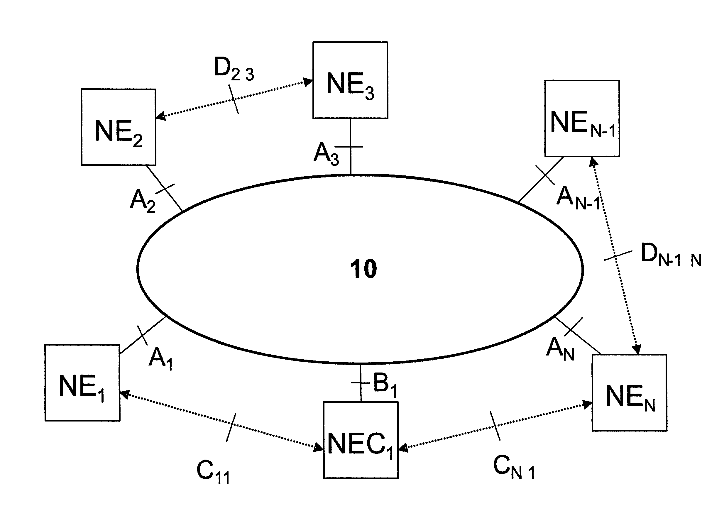
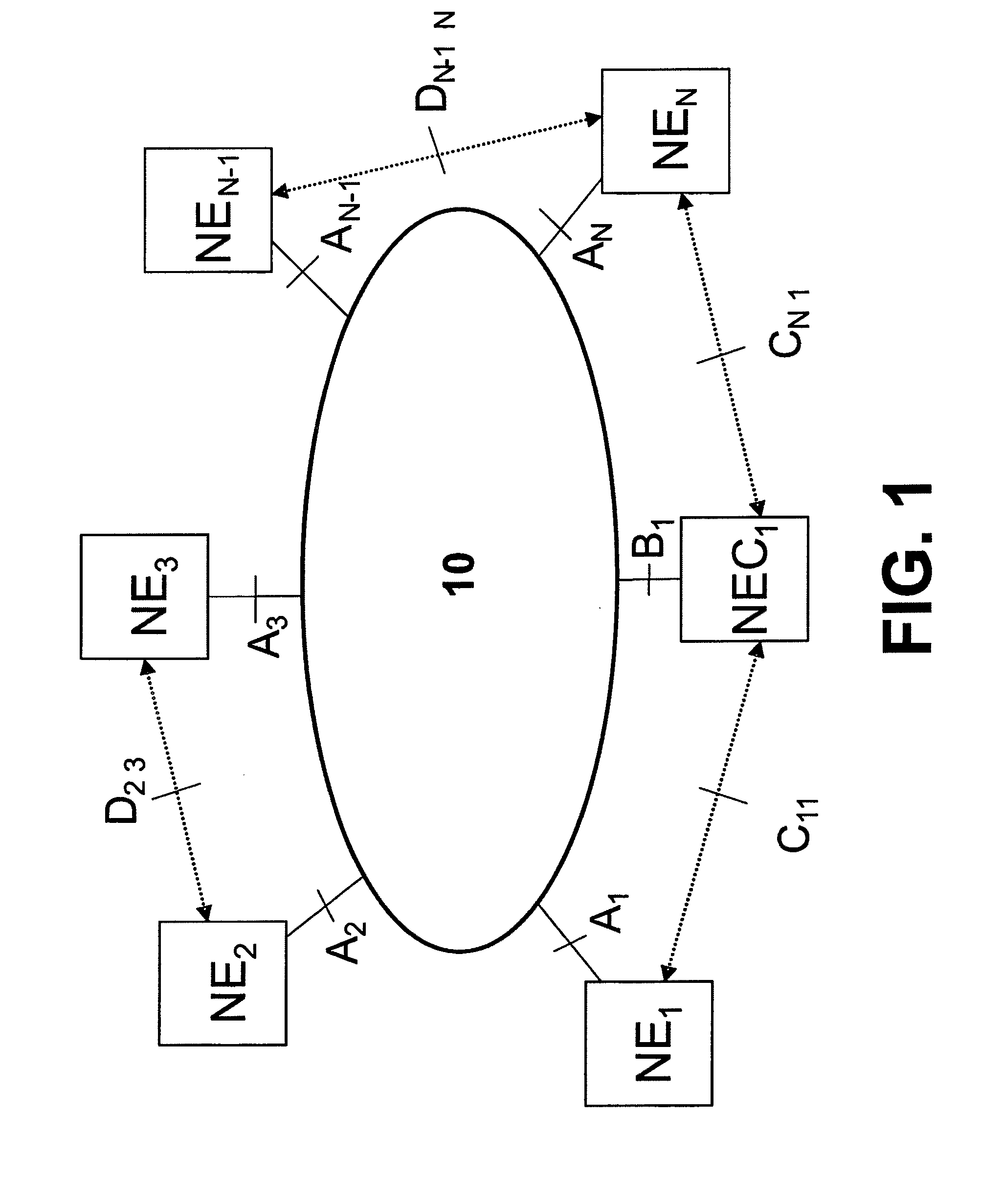
[0063]Here below a practical implementation of the invention is described, which is based on the general network architecture shown in FIG. 1. This general network architecture gathers:[0064]several network elements (NE1, . . . , NEi, . . . , NEj, . . . , NEN) connected to an IP Network (10) through a plurality of interfaces (A1, . . . , Ai, . . . , Aj . . . , AN), and[0065]several Network Elements Controllers (NEC1, . . . , NECk, . . . , NECQ) connected to the same IP Network (10) through another plurality of interfaces (B1, . . . , Bk, . . . , BQ).

[0066]These interfaces (A1, . . . , AN, B1, . . . , BQ) on the IP Network (10) with the network elements (NE1, . . . , NEi, . . . , NEj, . . . , NEN) and Network Elements. Controllers (NEC1, . . . , NECk, . . . , NECQ) respectively could be all of the same type, for example, Ethernet interfaces.

[0067]This IP Network (10) also provides a plurality of IP functional interfaces (Cik) from each network element (NEi) to the at least one networ...


PUM


Abstract

The method is applied to configure, reconfigure and monitor globally a plurality of network elements (NE1, . . . , NEi, . . . , NEj, . . . , NEN) connected to an IP Network (10) through multiple interfaces (A1, . . . , AN), with several Network Elements Controllers (NEC1, . . . , NECk, . . . , NECQ) connected to the same IP Network (10) through respective interfaces (B1, . . . , BQ). The IP Network (10) also provides a plurality of preconfigured IP functional interfaces (Cik) from each network element (NEi) to the at least one network elements controller (NECk). Each network element (NEi) has an IP networking layer (9) and runs / executes several network-related processes (P1, . . . , PL) managed and monitored by this method. The method also provides configuration and monitoring of IP interfaces (Dij) among network elements. The existing IP functional interfaces (Cik) are used to perform such managing and monitoring. To get these aims, the method performs high-level actions instead of atomic “get / set” operations. Neither the method neither requires explicit agents-manager paradigm nor depends on a particular communication protocol for network management.

Description

FIELD OF THE INVENTION[0001]The present invention is applied generally to the field of telecommunication networks and more particularly this invention relates to configuration, reconfiguration and monitoring of network nodes in networks providing Internet Protocol (IP) connectivity.[0002]More precisely, the present invention discloses a method for simplifying the task of logical deployment to configure a target IP network topology which is to be physically deployed on a background IP network, as well as the inverse task of logical undeployment is simplified. Furthermore, this method allows real time monitoring on the network elements previously deployed in, the target IP network.STATE OF THE ART[0003]Conventional management systems, such as Simple Network Management Protocol (SNMP) [D. Harrington, R. Presuhn, B. Wijnen, “An Architecture fot Describing Simple Network Management. Protocol (SNMP) Management Frameworks”, IETF Standard 62, RFC 3411, December 2002] or Web Based Enterprise...

Claims


Application Information

Patent Timeline
Patent Type & Authority Patents(United States)
IPC IPC(8): H04L12/28
CPCH04L41/0806H04L41/0843H04L41/0856H04L43/0811
Inventor GALAN MARQUEZ, FERMINMUNOZ GONZALEZ, RAUL
Owner FUNDACIO PRIVADA CENT TECNOLOGIC DE TELECOMUNICACIONS DE CATALUNYA
Learn More