Automated system problem diagnosing

a system problem and automatic diagnosis technology, applied in the field of system problem diagnosis, can solve problems such as system problems, system failures, power failures during adding hardware, etc., and achieve the effect of reducing the overhead of problem set similarity matching calculation and low similarity scor

Active Publication Date: 2012-02-07
GLOBALFOUNDRIES US INC
View PDF34 Cites 19 Cited by
  • Summary
  • Abstract
  • Description
  • Claims
  • Application Information

AI Technical Summary

Problems solved by technology

A system may encounter a problem which needs to be diagnosed.
System problems may include a software or application error, flaw, mistake, failure, or fault that prevents the software from operating as intended by producing an incorrect or unexpected result.
System problems may further include a firmware error such as a memory leak or a firmware bug.
System problems may further include an operating system configuration error such as an adapter port configuration problem or a Logical Unit Number (LUN) configuration problem.
System problems further includes a hardware error such as a power supply failure, a fan failure, a controller failure, or a storage failure.
System problems may further include a maintenance problem such as an adapter card failure during hardware replacement, power failure during adding hardware, or an internal power communication error during Remote Power Control (RPC) replacement.
System problems may further include a network problem such as a Transmission Control Protocol and Internet Protocol (TCP / IP) configuration error, a TCP / IP connectivity error, a gateway error, or Domain Name System (DNS) error.
For example, a computer may be running as expected, but may subsequently have a problem which causes the system to not operate as anticipated.
For example, a user may troubleshoot the system to find a problem.
Previously diagnosed problems may also require manual troubleshooting to determine and diagnose a system or an application problem.

Method used


Image

  • Automated system problem diagnosing
  • Automated system problem diagnosing
  • Automated system problem diagnosing

Examples


Embodiment Construction

[0020]The following description is made for the purpose of illustrating the general principles of the invention and is not meant to limit the inventive concepts claimed herein. Further, particular features described herein can be used in combination with other described features in each of the various possible combinations and permutations. Unless otherwise specifically defined herein, all terms are to be given their broadest possible interpretation including meanings implied from the specification as well as meanings understood by those skilled in the art and / or as defined in dictionaries, treatises, etc. For example, while the following description will be described in terms of system problem diagnosis processes, modules, and devices for clarity and to place the invention in context, it should be kept in mind that the teachings herein may have broad application to all types of systems, devices and applications.

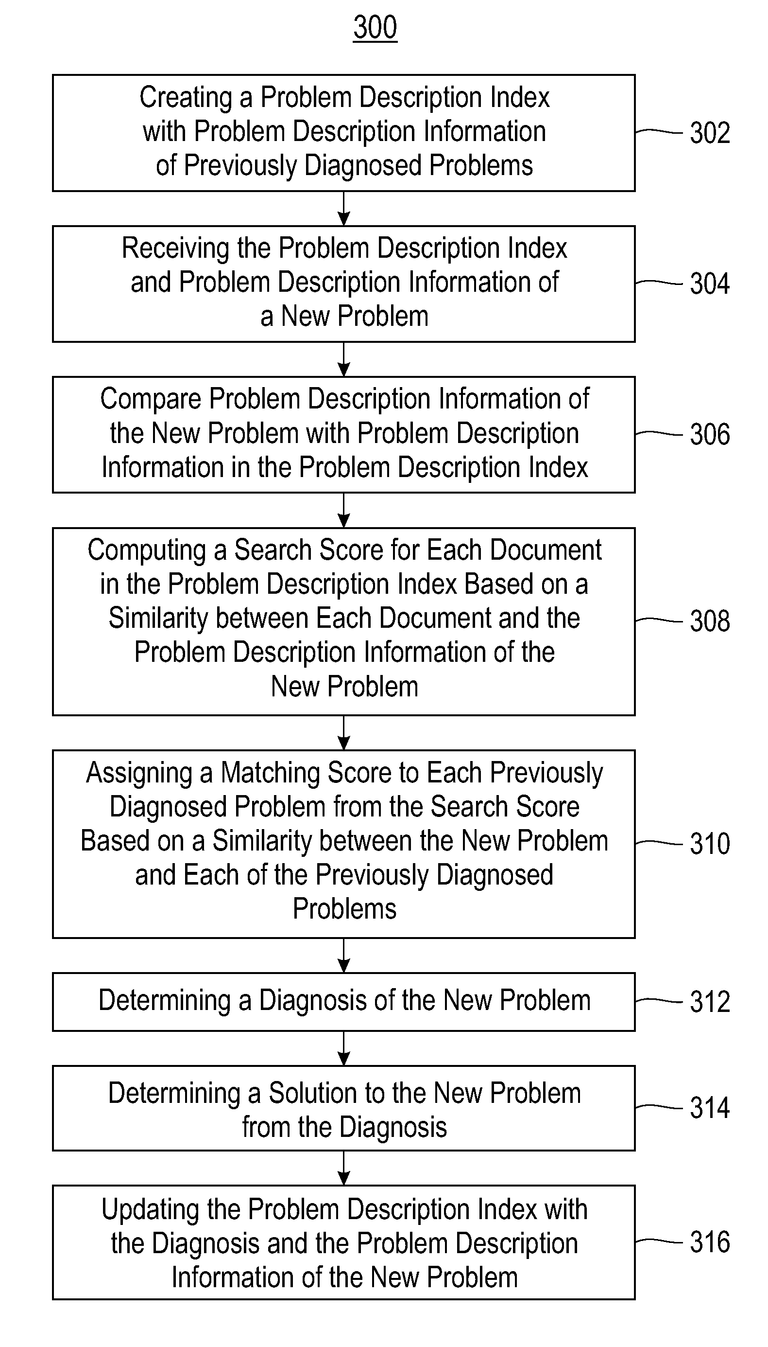
[0021]The embodiments of the invention relate to automated system probl...


PUM


Abstract

Embodiments of the invention relate to automated system problem diagnosing. An index is created with problem description information of previously diagnosed problems, a diagnosis for each problem, and a solution to each diagnosis. System states, traces and logs are extracted from a source system with a new problem. The problem diagnosis system generates problem description information of the new problem from the system states, traces and logs. Problem description information of the new problem is compared with problem description information in the problem description index. A search score is computed for each document in the problem description index. The search score is a measure of similarity between each document in the index and the description of the new problem. A matching score is assigned to each previously diagnosed problems based on the search score. The matching score is a measure of similarity between the new problem and each previously diagnosed problem. The system determines a diagnosis and solution of the new problem based on a diagnosis and solution of one of the previously diagnosed problems.

Description

BACKGROUND[0001]1. Field of the Invention[0002]Embodiments of the disclosure relate to the field of system problem diagnosis, and in particular, systems and methods for automatically diagnosing a system problem.[0003]2. Background of the Invention[0004]A system may encounter a problem which needs to be diagnosed. System problems may include a software or application error, flaw, mistake, failure, or fault that prevents the software from operating as intended by producing an incorrect or unexpected result. System problems may further include a firmware error such as a memory leak or a firmware bug. System problems may further include an operating system configuration error such as an adapter port configuration problem or a Logical Unit Number (LUN) configuration problem. System problems further includes a hardware error such as a power supply failure, a fan failure, a controller failure, or a storage failure. System problems may further include a maintenance problem such as an adapte...

Claims


Application Information

Patent Timeline
Patent Type & Authority Patents(United States)
IPC IPC(8): G06F11/00
CPCG06F11/079G06F17/30675G06F16/334
Inventor BELLUOMINI, WENDY ANNGILL, BINNY SHERYAN, XIFENGZHOU, PIN
Owner GLOBALFOUNDRIES US INC
Why Eureka
Try Eureka