

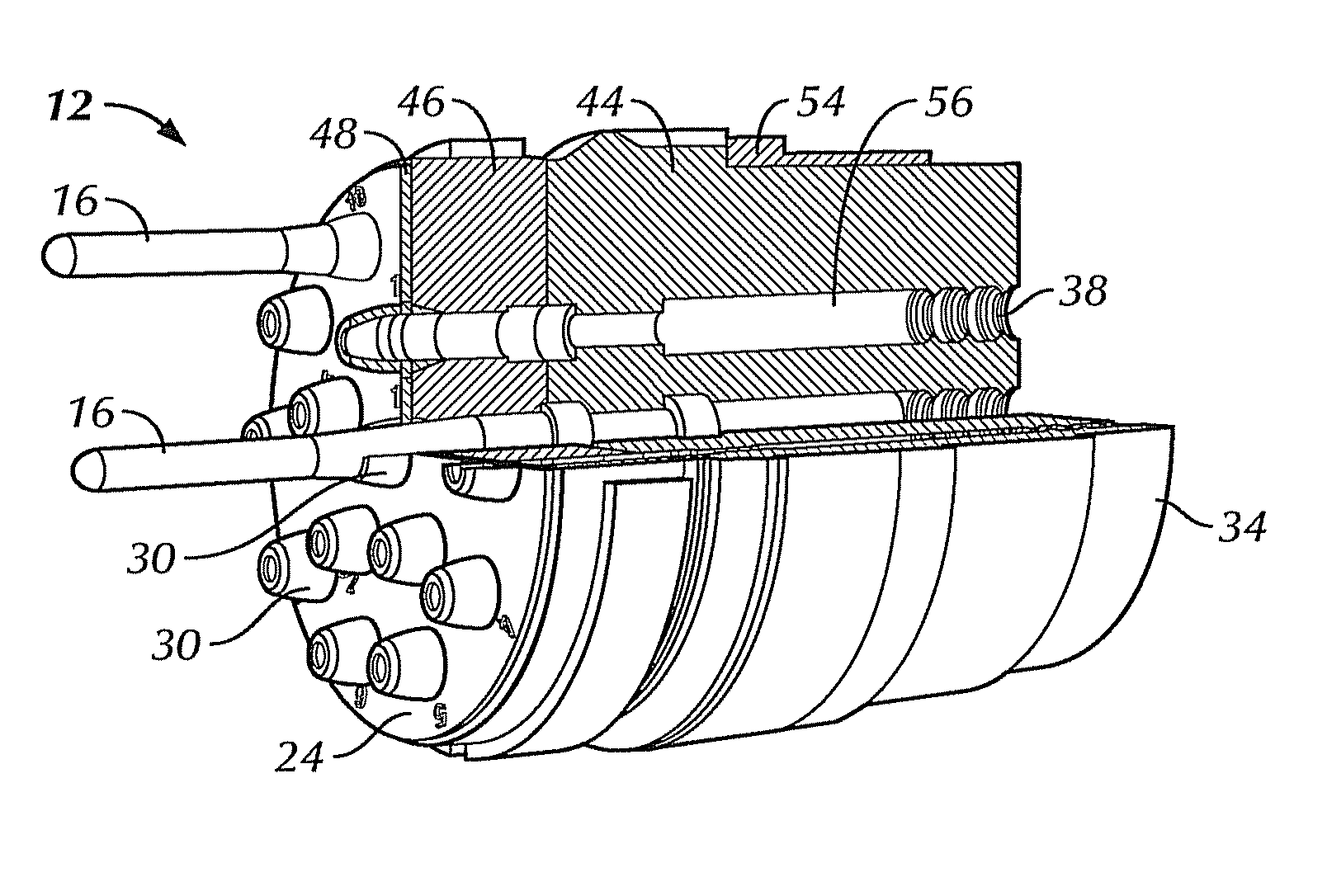
High power multi-pin electrical connector
a multi-pin, electrical connector technology, applied in the direction of coupling device connection, manufacturing tools, metal working apparatus, etc., can solve the problems of posing a significant challenge and probably futility, and achieve the effect of reducing the diameter of the socket, increasing or decreasing the diameter, and small for
- Summary
- Abstract
- Description
- Claims
- Application Information
AI Technical Summary
Benefits of technology
Problems solved by technology
Method used
Image

Examples
Embodiment Construction
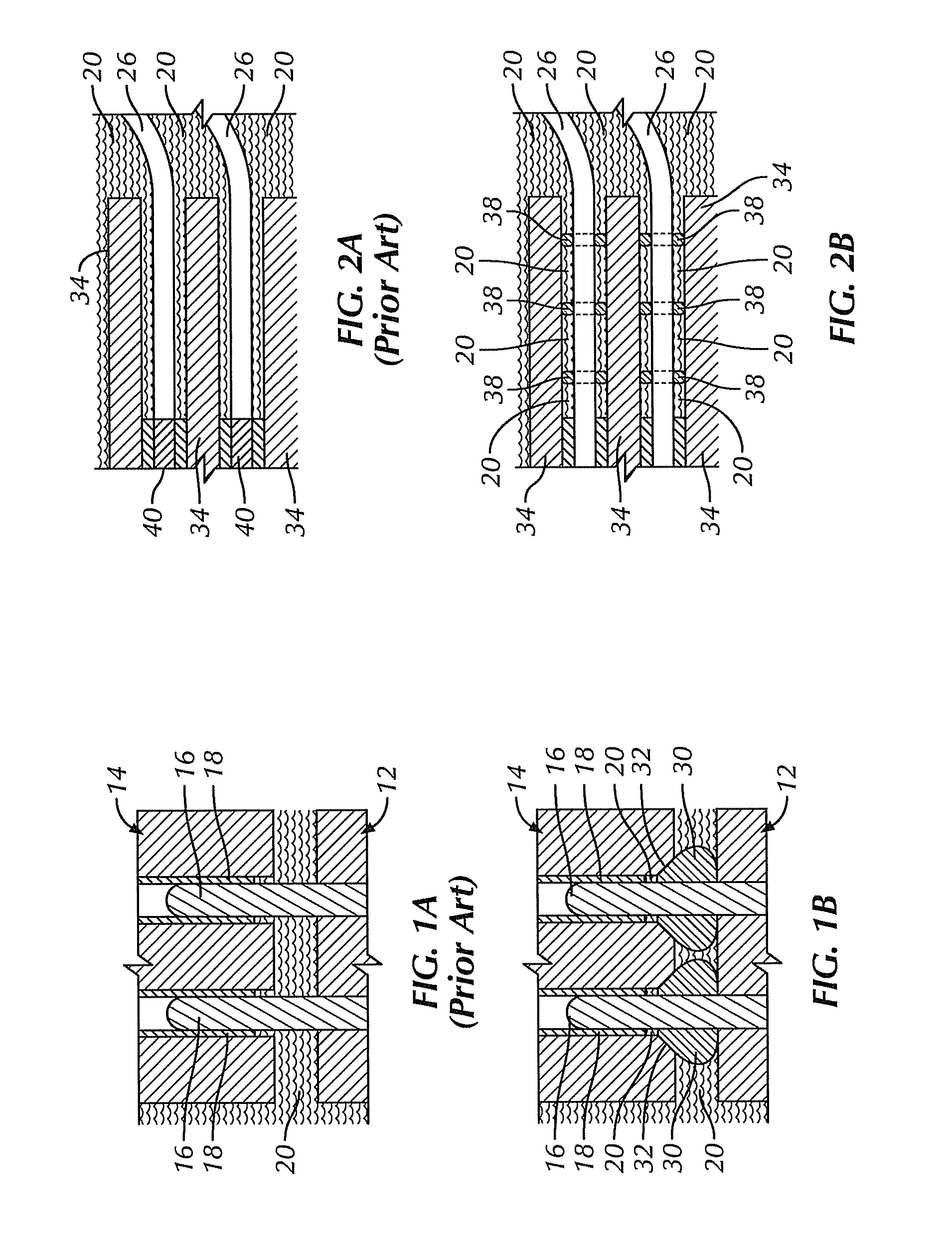
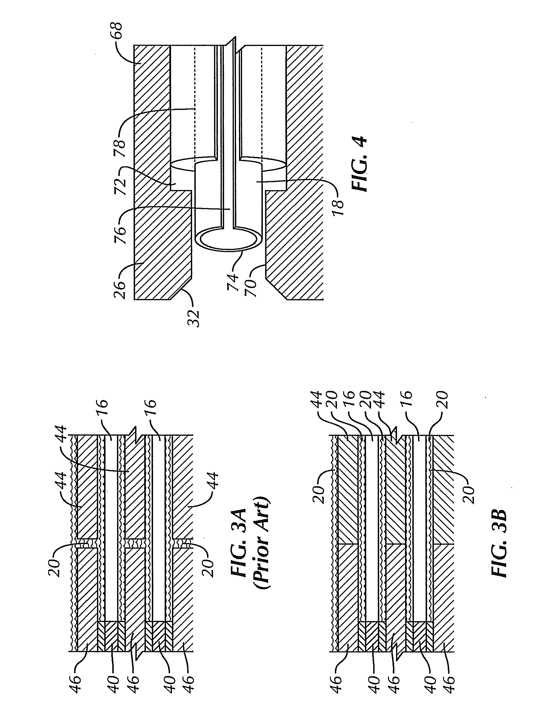
[0022]The problem water poses to multi-pin connectors is due to the electrical conductivity of the water and the numerous electrical contacts in close proximity to each other. The conductivity of water varies depending upon how many other substances are in the water. Pure water is a very poor conductor. But the water found in most industrial environments (e.g., sea water, rain, tap water, etc.) is a good enough conductor to pose problems.
[0023]A multi-pin electrical connector requires complete electrical isolation of each separate electrical line within the connector. Every pin and receptacle pair must be electrically isolated from all other pins and receptacles. If a continuous path of water exists between a conductor of one line and a conductor of another line, the water may form an electrical connection between the two conductors. This unintended and undesirable cross-connection between electrical contacts carrying separate signals creates cross talk.
[0024]The problem posed by cr...
PUM
| Property | Measurement | Unit |
|---|---|---|
| insulator | aaaaa | aaaaa |
| flexible | aaaaa | aaaaa |
| force | aaaaa | aaaaa |
Abstract
Description
Claims
Application Information