Hose hinge assembly

a technology of hinge assembly and hose, which is applied in the direction of couplings, bends, liquid transfer devices, etc., can solve the problems of difficult inspection, repair and/or replacement of components, and the bag needs to be folded and stowed directly, and achieves less maintenance.

Active Publication Date: 2010-02-09
GOLDMAN SACHS BANK USA AS SUCCESSOR COLLATERAL AGENT +1
View PDF18 Cites 0 Cited by
  • Summary
  • Abstract
  • Description
  • Claims
  • Application Information

AI Technical Summary

Benefits of technology

[0008]The present invention provides an emergency floatation system that includes a high-pressure hose hinge assembly that allows a portion of the emergency floatation system to be mounted to components that are hinged with respect to each other. In particular, the floats and valves may be coupled to a hinged compartment door of an aircraft while a pressurized fluid source is mounted inside the aircraft. The hose hinge assembly provides reliable fluid communication between the hinged parts which allows easy access to the system for inspection and / or replacement.
[0010]The present invention allows high pressure lines to extend between hinged components without requiring flexible tubing which may be more susceptible to bending fatigue, kinking and pinching. The present invention also allows the door to be opened without the need to disconnect the high pressure line and with minimal risk of failure due to bending and cycling when the door opens and closes.
[0011]According to an aspect of the present invention a high pressure pipe system allows operators to transfer gas from a fixed source to a movable component without compromising the original function of the moving component. This hinging pipe system can be used in connection with a baggage door life raft kit to inflate a life raft which is mounted in a pod on the inside of each baggage door which allows the baggage compartment to continue to be used for baggage without putting the integrity of the life raft system at risk.
[0012]During inflation of the life raft, gas is discharged from a remotely mounted reservoir and transferred via a series of inflation pipes, or hoses, to each baggage compartment door via the hose hinge assembly and then to the life raft pods. The hose hinge assembly would be the final connection point from the baggage compartment to the compartment door and the hinging mechanism allows the door to open without having to disconnect any pipes or hoses.
[0014]According to an aspect of the present invention, the swivel fittings are two 90-degree elbows connected by a rotating joint. The swivel fittings and rigid pipe sections define interior conduits and thereby provide a high pressure fluid path between the first and second portions of the high pressure line. The swivel fittings allow the door to be moved relative to the aircraft, without the pipe being subject to fatigue, kinking or wear.
[0015]The present invention provides many advantages over known systems. For example, the present invention allows the operator to attach an inflatable component (a float or life raft), or a hydraulic component, across an existing moving joint between components of a device without altering the original function of the moving component. Additionally, the hose hinge assembly replaces a flexible hose which is susceptible to pinching, kinking and binding. Another advantage is that high pressure line extending across the moving joint do not need to be removed to operate the joint. For example, where one end is coupled to a compartment and the other end is coupled to the compartment door, the line does not require disconnection in order to open the door. In addition, because rigid tubing is utilized, less maintenance is required due to the inherent reliability of the rigid pipe as compared to flexible piping.

Problems solved by technology

A first disadvantage of the system is that it requires the bags to be folded and stowed directly in the compartments.
As a result, inspection of the system would require removal of the bags from the compartment and re-stowing or replacement of the bags would require significant time so that the bags could be folded and stowed.
Another disadvantage is that the pressure cylinders are located within the airplane fuselage such that they are not readily accessible.
As a result, inspection, repair and / or replacement of those components is difficult.
A still further disadvantage is that it requires manual operation by the pilot even after the initial activation of the system.
A first disadvantage of the system is that it requires the life raft to be folded and stowed directly into a dedicated compartment.
As a result, inspection and / or replacement of the life raft may be difficult.
Another disadvantage of the system is that the pins may be disengaged without a complete activation of the system.
In addition, the pull cord may become bound which may result in the pin disengaging without activation of the gas container.
A further disadvantage is that the gas container valve does not include a mechanism to close the gas path between the gas container and the raft after the raft is inflated.
An additional disadvantage of the systems described above is that in order to retrofit an aircraft with such a system a compartment, such as a baggage compartment, would have to be converted and dedicated to the floatation system.

Method used


Image

  • Hose hinge assembly
  • Hose hinge assembly
  • Hose hinge assembly

Examples


Embodiment Construction

[0023]In the following paragraphs, the present invention will be described in detail by way of example with reference to the attached drawings. Throughout this description, the preferred embodiment and examples shown should be considered as exemplars, rather than as limitations on the present invention. As used herein, the “present invention” refers to any one of the embodiments of the invention described herein, and any equivalents. Furthermore, reference to various feature(s) of the “present invention” throughout this document does not mean that all claimed embodiments or methods must include the referenced feature(s).

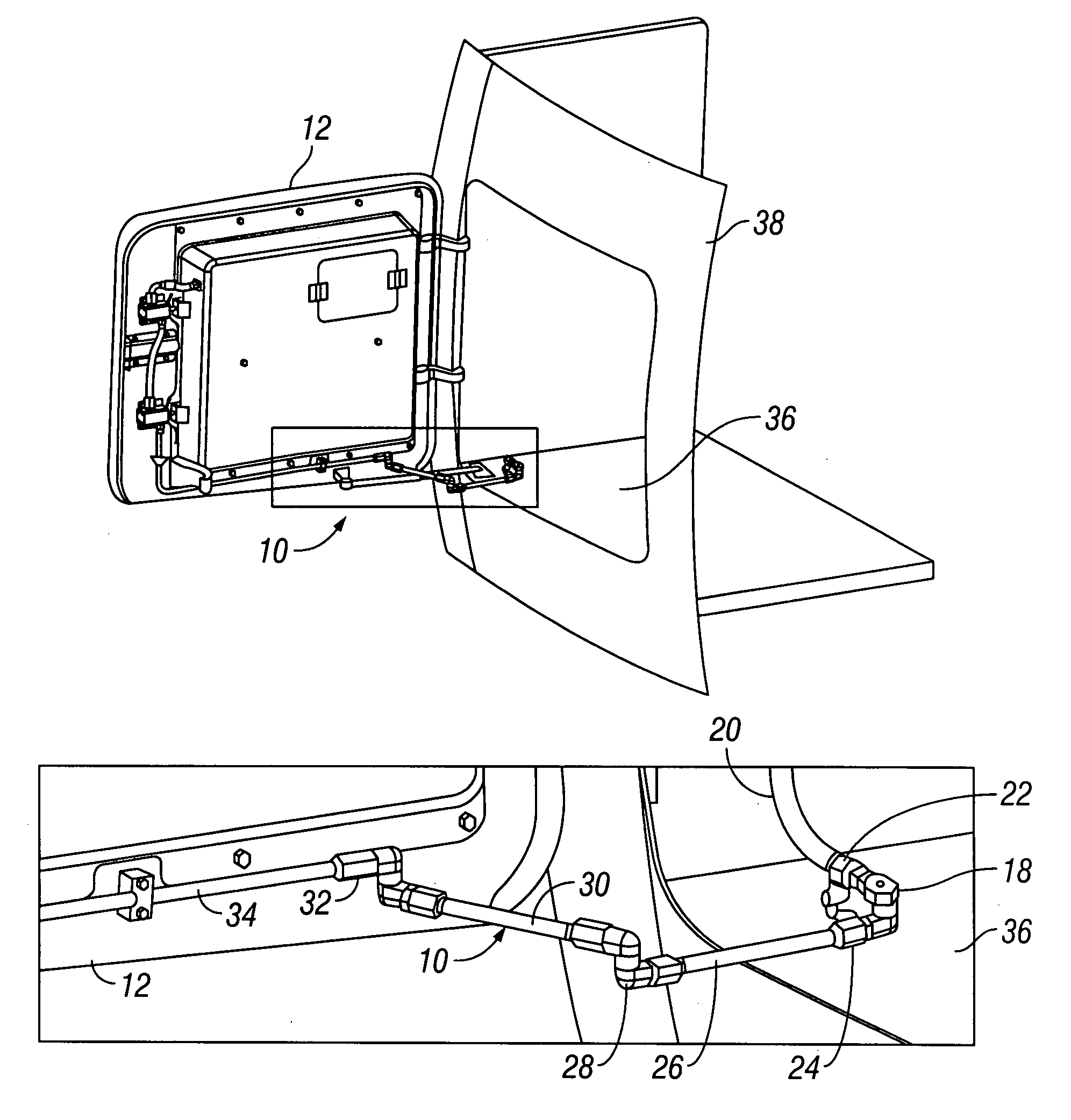
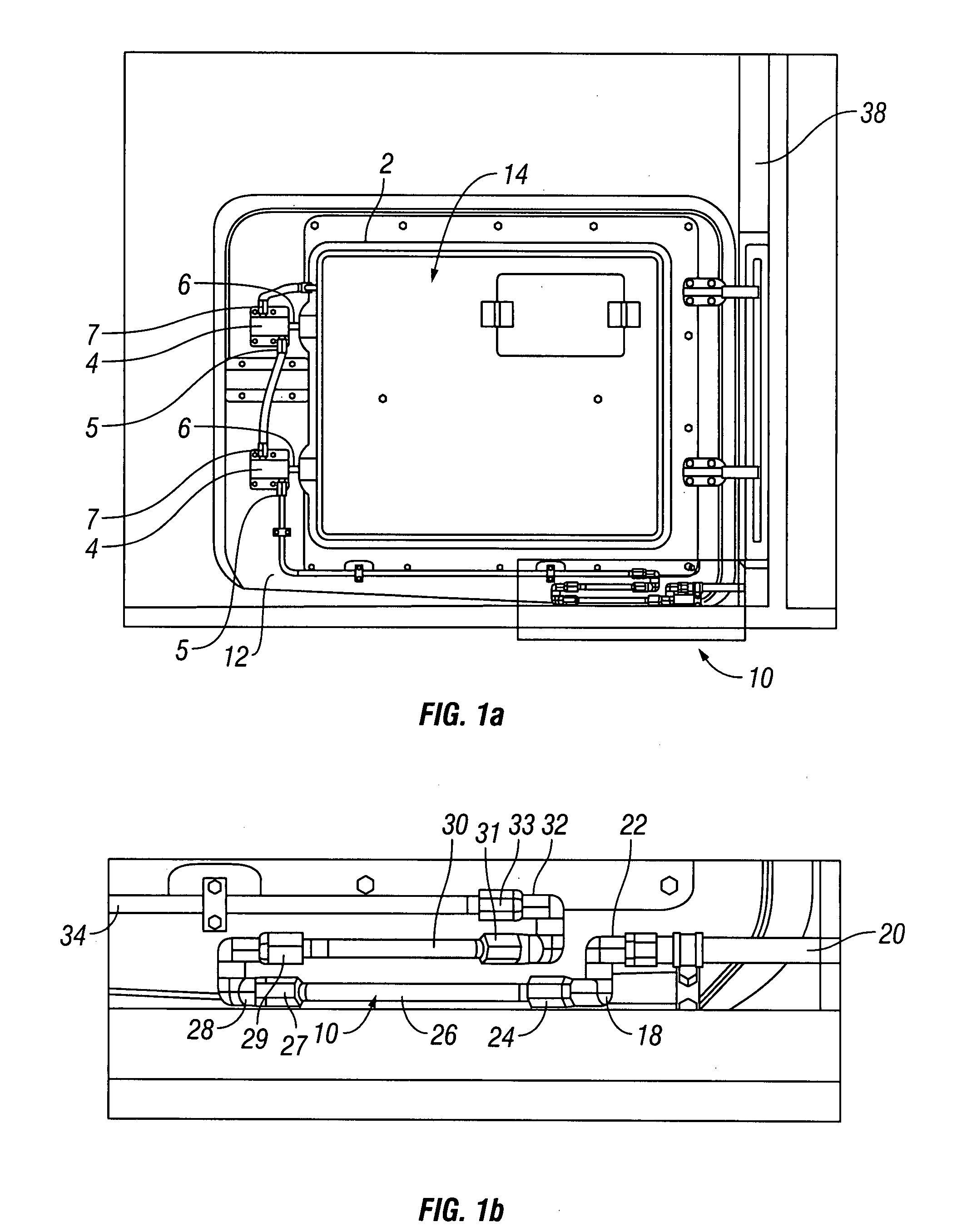
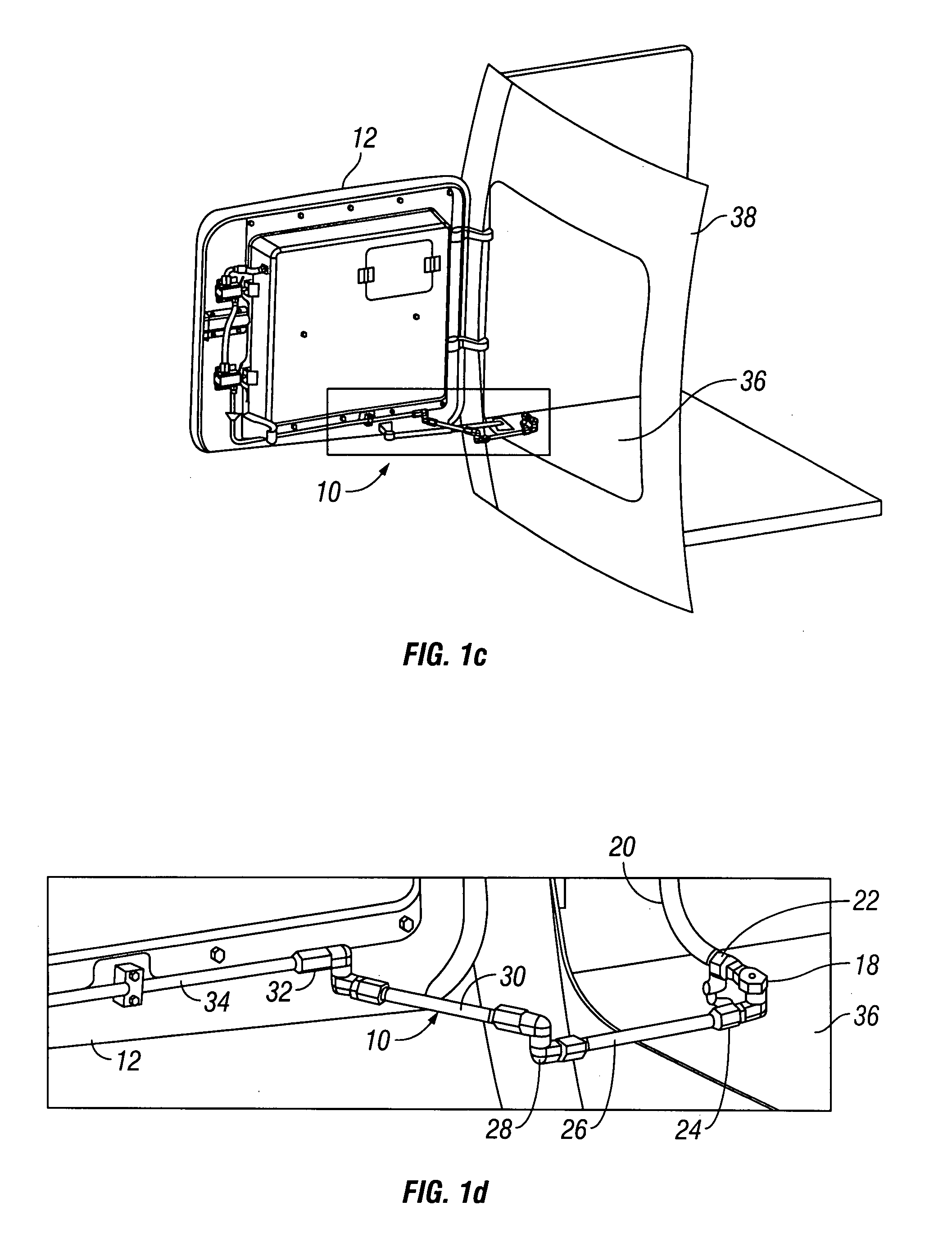
[0024]Referring initially to FIGS. 1a-d, the hose hinge assembly 10 is shown. Hose hinge assembly 10 is configured to allow a high-pressure fluid line to span between structural components that move relative to each other without being required to use flexible hose. In FIG. 1a, an emergency inflatable assembly, such as a life raft pod 14, is shown installed on an air...


PUM


Abstract

A high-pressure hose hinge assembly provides a continuous fluid path between first and second components that move relative to each other. The hose hinge assembly includes a plurality of rotatable swivel fittings that couple a plurality rigid pipe sections. A first swivel fitting is fixedly coupled to the first component and another swivel fitting is coupled to the second component. At least one swivel fitting and two rigid pipe sections extend between the swivel fittings coupled to the first and second components to provide a continuous fluid path.

Description

CROSS-REFERENCE TO RELATED APPLICATIONS[0001]This application claims priority to U.S. Provisional Patent Application Ser. No. 60 / 776,545, filed Feb. 24, 2006, which is hereby incorporated in its entirety by reference herein.FIELD OF THE INVENTION[0002]The present invention is generally directed to high pressure hose systems. More specifically, the present invention relates to a high pressure hose assembly that is hinged.BACKGROUND OF THE INVENTION[0003]Emergency flotation devices are required on many aircraft to provide emergency assistance to passengers in the event the aircraft experiences an emergency situation and is forced down in water. Emergency flotation devices generally include systems designed to float the aircraft, systems for emergency life rafts and life vests for individual occupants.[0004]One example of an airplane flotation system is shown in U.S. Pat. No. 1,776,865. The system includes inflatable bags located in a forward portion of an airplane and is manually oper...

Claims


Application Information

Patent Timeline
Patent Type & Authority Patents(United States)
IPC IPC(8): F16L27/00B64C1/14B67D7/00
CPCB67D7/002F16L27/0861F16L27/0845F16L27/0837
Inventor BARKER, DAVID N
Owner GOLDMAN SACHS BANK USA AS SUCCESSOR COLLATERAL AGENT
Why Eureka
Try Eureka