Optical imaging system with catoptric objective; broadband objective with mirror; and refractive lenses and broadband optical imaging system having two or more imaging paths

an optical imaging system and optical imaging technology, applied in the field of imaging optics, can solve the problems of limited availability of manufacturable anti-reflective (ar) coating materials effective over the spectrum from sub-200 nm to above 400 nm wavelength, and the risk of contamination deposition onto the wafer and/or diffusion, etc., to achieve improved manufacturability, low central obscuration, and high numerical aperture

Active Publication Date: 2011-10-06
KLA TENCOR TECH CORP
View PDF1 Cites 31 Cited by
  • Summary
  • Abstract
  • Description
  • Claims
  • Application Information

AI Technical Summary

Benefits of technology

[0015]In certain embodiments of the present invention, an outermost mirror of an objective for an imaging system such as a wafer inspection system may have improved manufacturability by decreasing its aspect ratio at a sample side to between about 10:1 and about 20:1. This allows inspection with a more manufacturable objective of high Numerical Aperture (NA), greater than 0.7, with large Field of View (FOV), greater than 0.5 mm, low central obscuration (e.g., less than 35%, less than 30% or less than 25%), broadband spectrum below 250 nm, and requiring no more than 6 mirrors. Such a system may further utilize one or more refractive elements in the pupil relay and imaging optics external to the objective, in order to improve the system flexibility and efficiency. The refractive elements in the pupil relay and imaging optics minimize the constraints on the packaging, and create the opportunity for aberration compensation to the objective, thereby lowering the tolerance requirements. According to one embodiment, the objective may be a 4 mirror objective. Another embodiment of the invention may utilize a 6 mirror objective. Both embodiments have more manufacturable outermost elements, with two configurations thereof A refractive pupil relay that can be modified to be used with either of the two embodiments of the inventive objective is also disclosed.
[0016]Additional embodiments of the present invention improve upon the manufacturability, photo-contamination control, optical performance and wafer edge inspection of the front element of a reflective broadband objective by providing a refractive element that closes the opening closest to the sample, thereby improving photo-contamination control (PCC). Some embodiments of the present invention utilize a refractive optical module in a central opening of a reflective element closest to a sample. In some embodiments of the present invention the refractive optical element is a curved refractive shell-like lens element. According to an embodiment of the present invention, an imaging objective may comprise two or more mirrors, at least one of which contains a refractive module that seals off a central opening of an outermost mirror of the two or more mirrors in order to substantially isolate an atmosphere inside the objective from a sample atmosphere.
[0017]In some embodiments, the refractive element can be less curved, and even closer to being flat. The refractive module can also consist of more than one refractive element. Embodiments of the present invention may utilize refractive optical elements to redistribute field curvature contributions from the reflective elements of the objective, thereby improving mirror manufacturability. The reflective and refractive elements in the objective may be configured such that the angle of incidence (AOI) on the refractive elements is less than about 25 degrees to reduce the complexity of the broadband anti-reflective (AR) coating and improve the achievable AR performance.
[0018]Further embodiments of this invention may provide an apparatus and method for providing simultaneous defect inspection data from multiple wavelength bands, Bright Field (BF) and Dark Field (DF), differing magnifications, and independent alignment and magnification adjustment. These features provide more efficient utilization of imaging resources, allow for simultaneous high sensitivity BF inspection and better light-budget DF inspection.

Problems solved by technology

Furthermore, the availability of manufacturable Anti-Reflective (AR) coating materials effective over the spectrum from sub-200 nm to above 400 nm wavelength is limited.
These conditions make it extremely difficult to design and manufacture an all-refractive or catadioptric optical system that supports broadband illumination and detection including wavelengths shorter than 250 nm.
The presence of the opening presents a potential risk of deposition of contaminants onto the wafer and / or diffusion of contaminations into the objective.
Such contamination risks are undesirable in wafer inspection systems.
However, this creates mechanical instabilities at or near the opening.
However, it may be difficult to implement this method in a broadband system that includes wavelengths below 200 nm due to color correction, AR performance issues and or mechanical instability if the window is made too thin.

Method used


Image

  • Optical imaging system with catoptric objective; broadband objective with mirror; and refractive lenses and broadband optical imaging system having two or more imaging paths
  • Optical imaging system with catoptric objective; broadband objective with mirror; and refractive lenses and broadband optical imaging system having two or more imaging paths
  • Optical imaging system with catoptric objective; broadband objective with mirror; and refractive lenses and broadband optical imaging system having two or more imaging paths

Examples


Embodiment Construction

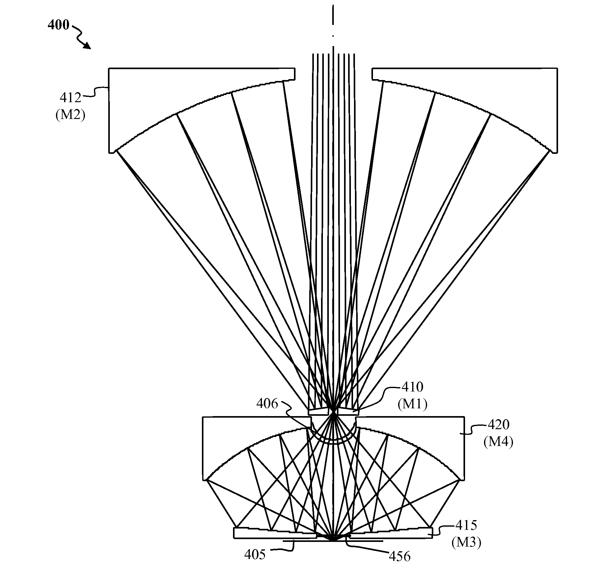
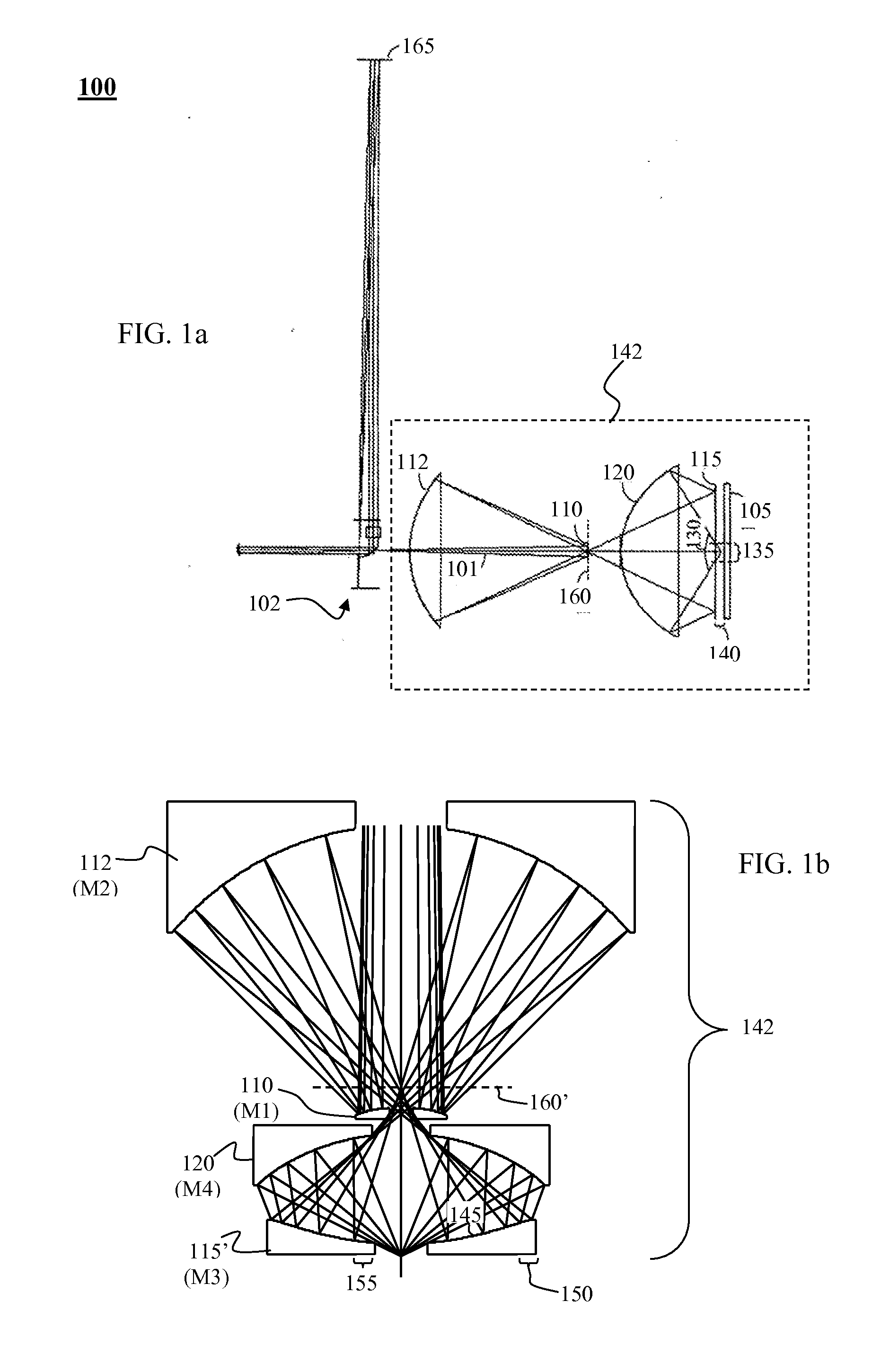
[0040]FIG. 1a depicts an example of an optical imaging system 100 that uses a 4-mirror objective design based on the one disclosed in US Patent publication 2006 / 0219930. The optical system depicted in FIG. 1a includes a pupil relay portion 102 and an objective portion 142. The objective portion 142 includes mirrors 110 (M1), 112 (M2), 115 (M3) and 120 (M4). An incident light beam 101 from the pupil relay portion 102 impinges first onto mirror 110 (M1), then mirror 112 (M2), then an outermost mirror 115 (M3), then mirror 120 (M4), then onto sample 105. The sample is generally located close to the outermost mirror 115 in a sample inspection system, such as a wafer inspection system or biological specimen inspection system or mask inspection system. The nomenclature as utilized herein may be construed as a definition of the terms denoting the relative positions of the mirrors within the example being illustrated, i.e., the numbering of the mirrors is defined by the order in which the i...


PUM

PropertyMeasurementUnit
aspect ratioaaaaaaaaaa
sizeaaaaaaaaaa
angle of incidenceaaaaaaaaaa

Abstract

An optical system may include an objective having at least four mirrors including an outermost mirror with aspect ratio <20:1 and focusing optics including a refractive optical element. The objective provides imaging at numerical aperture >0.7, central obscuration <35% in pupil. An objective may have two or more mirrors, one with a refractive module that seals off an outermost mirror's central opening. A broad band imaging system may include one objective and two or more imaging paths that provide imaging at numerical aperture >0.7 and field of view >0.8 mm. An optical imaging system may comprise an objective and two or more imaging paths. The imaging paths may provide two or more simultaneous broadband images of a sample in two or more modes. The modes may have different illumination and/or collection pupil apertures or different pixel sizes at the sample.

Description

CLAIM OF PRIORITY[0001]This application claims the priority benefit of U.S. Provisional Patent Application No. 60 / 997,306, filed Oct. 2, 2007, the entire disclosures of which are incorporated by reference herein. This application also claims the priority benefit of U.S. Provisional Patent Application No. 61 / 000,254, filed Oct. 24, 2007, the entire disclosures of which are incorporated by reference herein.[0002]This application claims the priority benefit of International Patent Application No. PCT / US2008 / 078493, which was filed on Oct. 1, 2008, the entire disclosures of which are incorporated herein by reference.FIELD OF THE INVENTION[0003]This invention relates to imaging optics for sample inspection, and in particular to the use of catoptric objectives, catadioptric objectives, and the use of multiple wavelength bands and / or inspection modes simultaneously.BACKGROUND OF THE INVENTION[0004]Defect inspection for the DUV range is currently being performed with all-refractive objectiv...

Claims


Application Information

Patent Timeline
Patent Type & Authority Applications(United States)
IPC IPC(8): G01N21/88G02B17/08
CPCG01N21/9501G03F1/84G02B17/084
Inventor HWANG, SHIOW-HWEIKIRK, GREGORY L.JEONG, HWAN J.SHAFER, DAVIDHUDYMA, RUSSELL
Owner KLA TENCOR TECH CORP
Why Eureka
Try Eureka