Dual-ring tubular lock assembly

a tubular lock and double ring technology, applied in the direction of latching locks, building locks, constructions, etc., can solve the problems of poor security of conventional tubular locks and inability to undo locks, and achieve the effect of increasing or decreasing the number of inner ring notches, outer ring notches and key pins, and simple structur

Active Publication Date: 2018-04-17
XIAMEN MAKE LOCKS MFGR CO LTD
View PDF22 Cites 1 Cited by
  • Summary
  • Abstract
  • Description
  • Claims
  • Application Information

AI Technical Summary

Benefits of technology

[0004]The primary object of the present invention is to provide a dual-ring tubular lock assembly which has a simple structure and high security.
[0011]According to the aforesaid, the present invention has a simple structure. The inner and outer walls of the key are respectively formed with the inner-ring notches and the outer-ring notches by milling. The inner-ring key pins, the outer-ring key pins, the inner-ring driver pins, and the outer-ring driver pins are mounted corresponding to the inner-ring notches and the outer-ring notches. With the increase or decrease in diameter of the tubular key, the number of the inner-ring notches, the outer-ring notches and the key pins is increased or decreased and the number of the variations of the key bittings is also increased or decreased. Moreover, the dual-ring structure of the tubular lock increases the number of the variations of the key bitting greatly to improve the security of the lock. The use of different levels of the pins increases the difficulty of unlocking.

Problems solved by technology

If the key is incorrect, it is unable to undo the lock.
The number of the variations of the key bittings is few, so the security of the conventional tubular lock is poor.

Method used


Image

  • Dual-ring tubular lock assembly
  • Dual-ring tubular lock assembly
  • Dual-ring tubular lock assembly

Examples


Embodiment Construction

[0022]Embodiments of the present invention will now be described, by way of example only, with reference to the accompanying drawings.

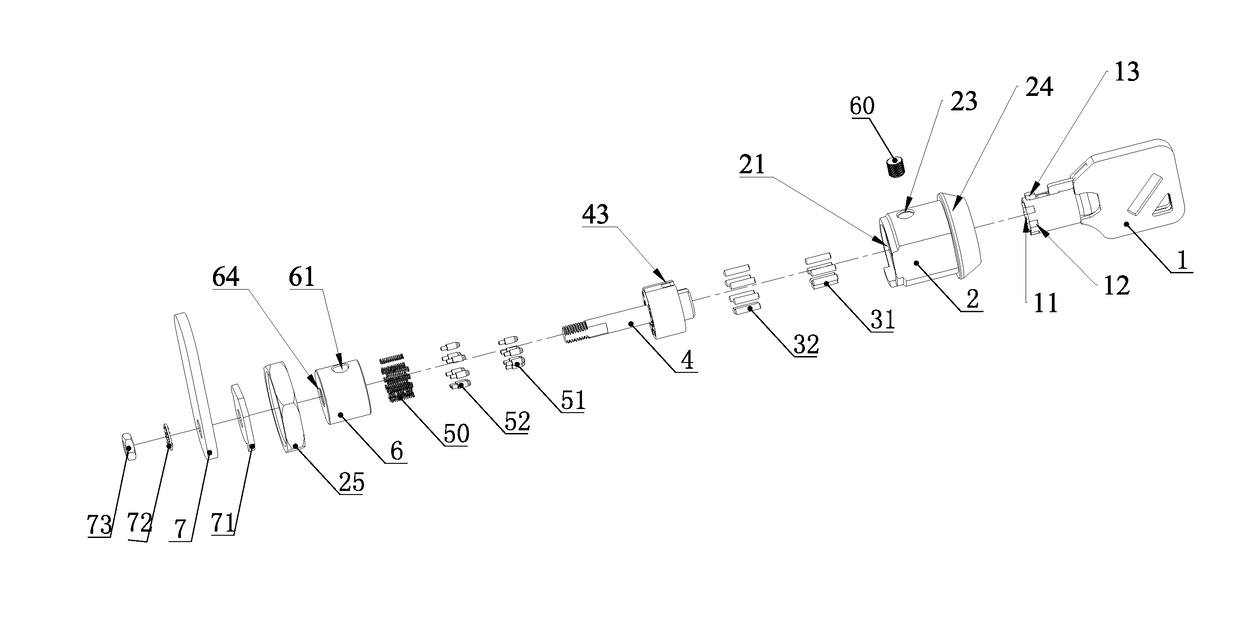
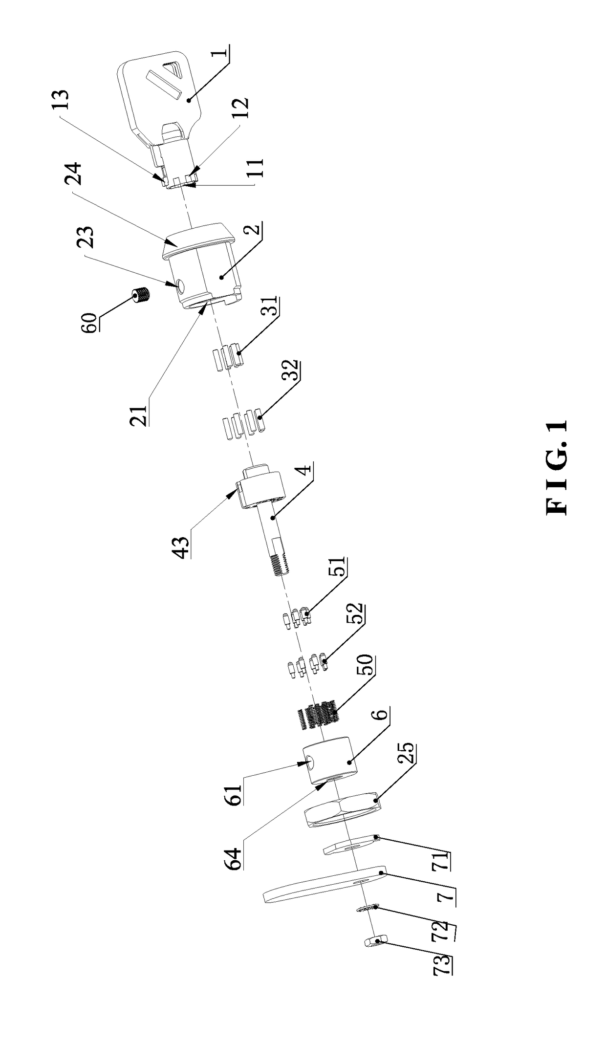
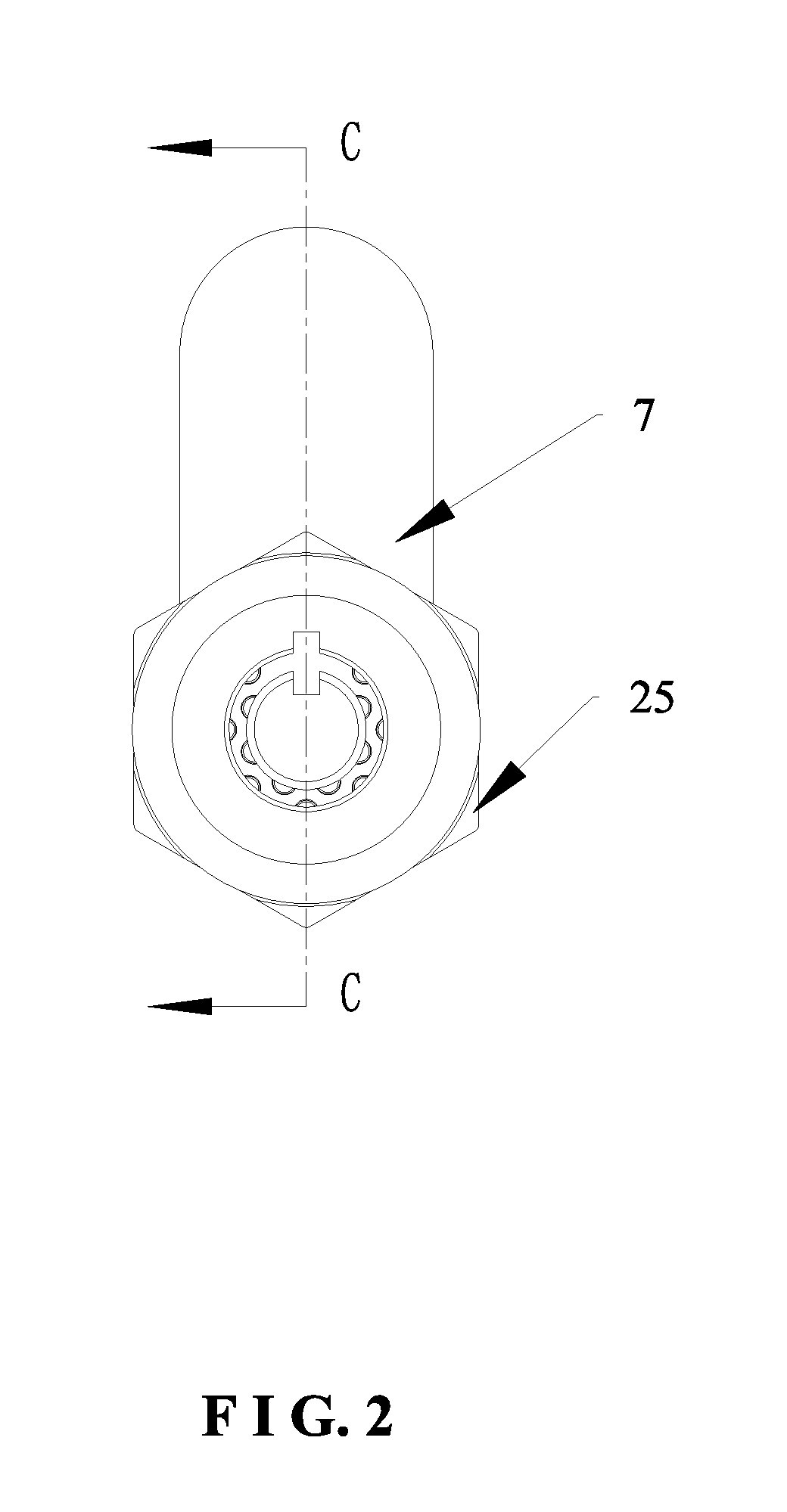
[0023]As shown in FIG. 1 to FIG. 10, the present invention discloses a dual-ring tubular lock assembly comprises a key 1, a lock housing 2, inner-ring key pins 31, outer-ring key pins 32, a lock cylinder 4, inner-ring driver pins 51, outer-ring driver pins 52, springs 50, a lower bead seat 6, and a latch 7.

[0024]The key 1 is tubular in shape. An inner wall and an outer wall of the tubular key 1 are formed with inner-ring notches 11 and outer-ring notches 12, respectively. The inner wall and the outer wall of the tubular key 1 may be circular or polygonal.

[0025]The lock housing 2 has a central through hole 21. A front end of the central through hole 21 is formed with a stop step 22 which serves to block the lock cylinder 4 from coining out.

[0026]The lock cylinder 4 is movably inserted in the central through hole 21. A front end of the lock cylinder 4 i...


PUM


Abstract

A dual-ring tubular lock assembly is provided. Inner and outer walls of a key are formed with inner-ring and outer-ring notches. A lock cylinder is inserted in a central through hole of a lock housing. A front end of the lock cylinder is formed with a tubular keyhole. The tubular keyhole is formed with inner-ring and outer-ring grooves corresponding to the inner-ring and outer-ring notches and mounted with inner-ring and outer-ring key pins. A rear end of the lock cylinder passes through a central perforation of a lower bead seat and extends out of the lock housing. The lower bead seat is fixed in the center through hole. The lower bead seat is formed with inner-ring and outer-ring holes corresponding to the inner-ring and outer-ring grooves and mounted with inner-ring and outer-ring driver pins and springs. The latch is fixed to the rear end of the lock cylinder.

Description

BACKGROUND OF THE INVENTION1. Field of the Invention[0001]The present invention relates to a dual-ring tubular lock assembly.2. Description of the Prior Art[0002]A tubular lock has a tubular key hole, and the corresponding key is tubular in shape. When the correct tubular key is inserted into the tubular keyhole, the key pushes the pins in the lock to a specific position, allowing the lock cylinder to turn relative to the lock housing, and then the lock cylinder drives the latch to turn so as to undo the lock. If the key is incorrect, it is unable to undo the lock.[0003]Only the outer edge of the tubular key is formed with notches, and only the outer wall of the tubular keyhole is mounted with pins. The number of the variations of the key bittings is few, so the security of the conventional tubular lock is poor. Accordingly, the present invention intends to provide a dual faucet structure for improving the shortcomings mentioned above.SUMMARY OF THE INVENTION[0004]The primary object...

Claims


Application Information

Patent Timeline
Patent Type & Authority Patents(United States)
IPC IPC(8): E05B19/02E05B55/00E05B27/08E05B9/04E05B19/00
CPCE05B55/005E05B9/041E05B19/0047Y10T70/7853E05B27/083Y10T70/7593E05B27/08E05C3/042
Inventor ZHANG, JIEHAO
Owner XIAMEN MAKE LOCKS MFGR CO LTD
Why Eureka
Try Eureka