
Remote application linking infrastructure

a remote application and application technology, applied in the field of remote application linking infrastructure, can solve the problems of users in a single domain from accessing citrix-based applications, and achieve the effect of simple implementation, support, and scaling up

Active Publication Date: 2012-02-14
SOUTHERN COMPANY SERVICES
View PDF18 Cites 12 Cited by
  • Summary
  • Abstract
  • Description
  • Claims
  • Application Information

AI Technical Summary

Benefits of technology

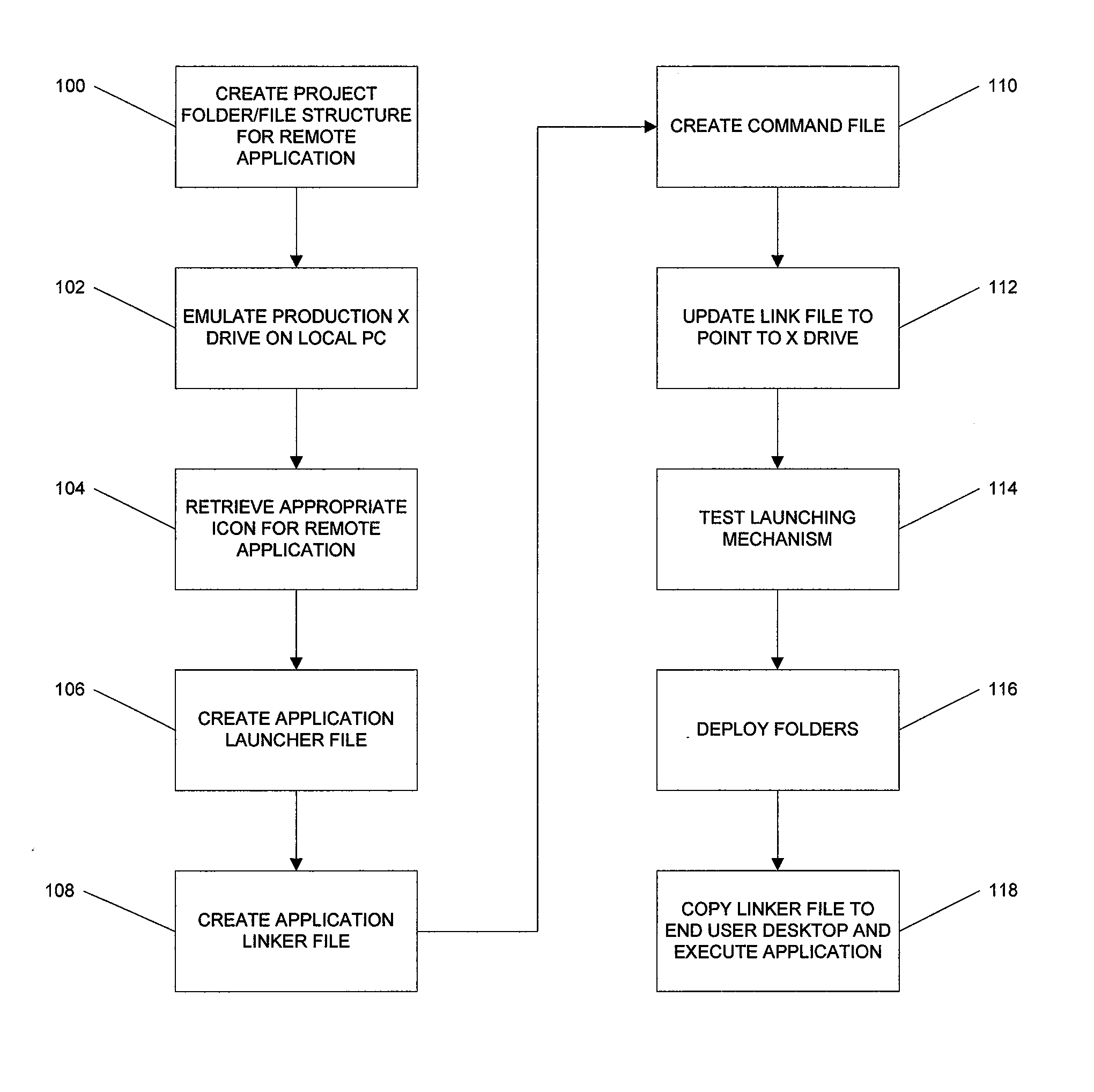
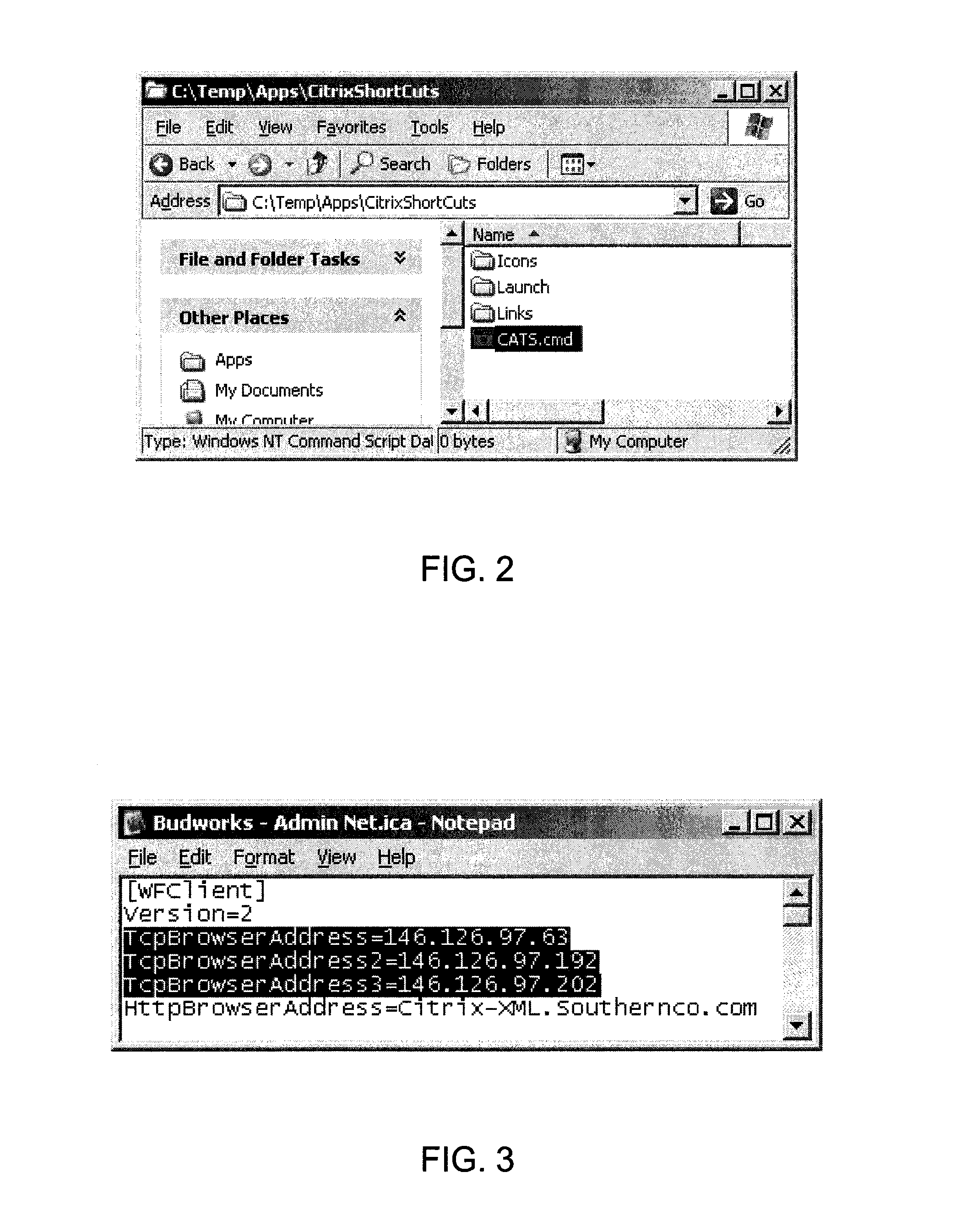
[0004]In embodiments of the invention, a short cut or “linker” file is installed onto the end user's desktop that points out to the user's X drive for all of its configuration information. An “X” drive is just a generic drive letter assignment used as a convenient designation in the present application. This is a file server mapping that is created for all of the client PC's during the logon process. This mechanism, a file server drive mapping to the remote application linking infrastructure data, makes embodiments of the invention far simpler to implement, support, and scale up in an enterprise environment. The configuration information includes the icon that it uses so that the end user can readily identify the application linker file that is used to instantiate the remote Citrix application session.

Problems solved by technology

Since the firewall rules that would have to be put in place to allow these employees to access the software applications from their desktops would have been very broad, and there was no way for them to be fully segregated from the rest of the power company's computer data network, these applications are run from remote servers located outside the power company's primary and non-segregated network.
However, the embodiments described herein prevent employee users in a single domain from accessing Citrix-based applications that they are not permitted to run even though those Citrix-based applications are “published” or available to all users within that single domain.

Method used


Image

  • Remote application linking infrastructure
  • Remote application linking infrastructure
  • Remote application linking infrastructure

Examples


Embodiment Construction

[0013]The following description of the invention is provided as an enabling teaching of the invention and its best, currently known embodiments. Those skilled in the relevant art will recognize that many changes can be made to the embodiments described, while still obtaining the beneficial results. It will also be apparent that some of the desired benefits of the embodiments described can be obtained by selecting some of the features of the embodiments without utilizing other features. Accordingly, those who work in the art will recognize that many modifications and adaptations to the embodiments described are possible and may even be desirable in certain circumstances, and are a part of the invention. Thus, the following description is provided as illustrative of the principles of the embodiments of the invention and not in limitation thereof, since the scope of the invention is defined by the claims.

[0014]Briefly, in the embodiments of the invention described herein, the end user ...


PUM


Abstract

A method, system, and computer readable medium for controlling user access from a segmented network to shared remote applications stored on a remote server. The method begins by generating a folder / file structure for a remote application that is to be shared on the segmented network. A file server drive mapping to a linking infrastructure data is generated for the remote application and an icon associated with the remote application is retrieved. An application launcher file is generated for the remote application. Then, an application linker file associated with the application launcher file for the remote application is generated. A command file is generated for copying the application linker file to a user's desktop. The linker file is updated to point to the file server drive. A folder for user access to the remote application is then deployed that includes the remote application icon, the application linker file, the application launcher file, and the command file.

Description

BACKGROUND OF THE INVENTION[0001]Embodiments of the invention relate generally to providing controlled access to software applications and, more particularly, to providing controlled access to software applications resident on servers external to an enterprise network.[0002]In a large enterprise, it often becomes necessary to segregate the application access rights of certain users in a domain from all other users in the domain. For example, in electric power companies, the Federal Energy Regulatory Commission has mandated that certain power company employees be segmented from the rest of the power company's data network to prevent those employees from gaining inside information about electricity generation and / or transmission. However, those same employees would still need to be able to access a number of different software applications to perform their day to day jobs. Since the firewall rules that would have to be put in place to allow these employees to access the software appli...

Claims


Application Information

Patent Timeline
Patent Type & Authority Patents(United States)
IPC IPC(8): G06F17/30
CPCG06F9/44521
Inventor SHELBY, III, DAVID C.
Owner SOUTHERN COMPANY SERVICES
Learn More