
Cutter adapter for cutting machine

a technology of cutting machine and cutter, which is applied in the field of cutting machine, can solve the problems of user hand being subjected, operation inconvenience, and further potentially hurting the user

Inactive Publication Date: 2012-02-21
MOBILETRON ELECTRONICS
View PDF6 Cites 14 Cited by
  • Summary
  • Abstract
  • Description
  • Claims
  • Application Information

AI Technical Summary

Benefits of technology

The present invention provides a cutter adapter for a cutting machine that allows the user to easily connect and disconnect the cutter without having to apply excessive force. The cutter adapter also prevents the user from potentially injury and reduces the time and effort required to replace the cutter. The cutter adapter includes a holder, a lock pin, a sleeve, a biasing pin, a first spring, and a second spring. The holder is connected to the drive shaft of the cutting machine and has two receiving portions for the cutter. The lock pin is movable between a first position and a second position to secure the cutter. The sleeve is moved between a third position and a fourth position to move the lock pin. The biasing pin keeps the lock pin in the first position and the first spring keeps the sleeve in the fourth position. The second spring keeps the biasing pin in the sixth position.

Problems solved by technology

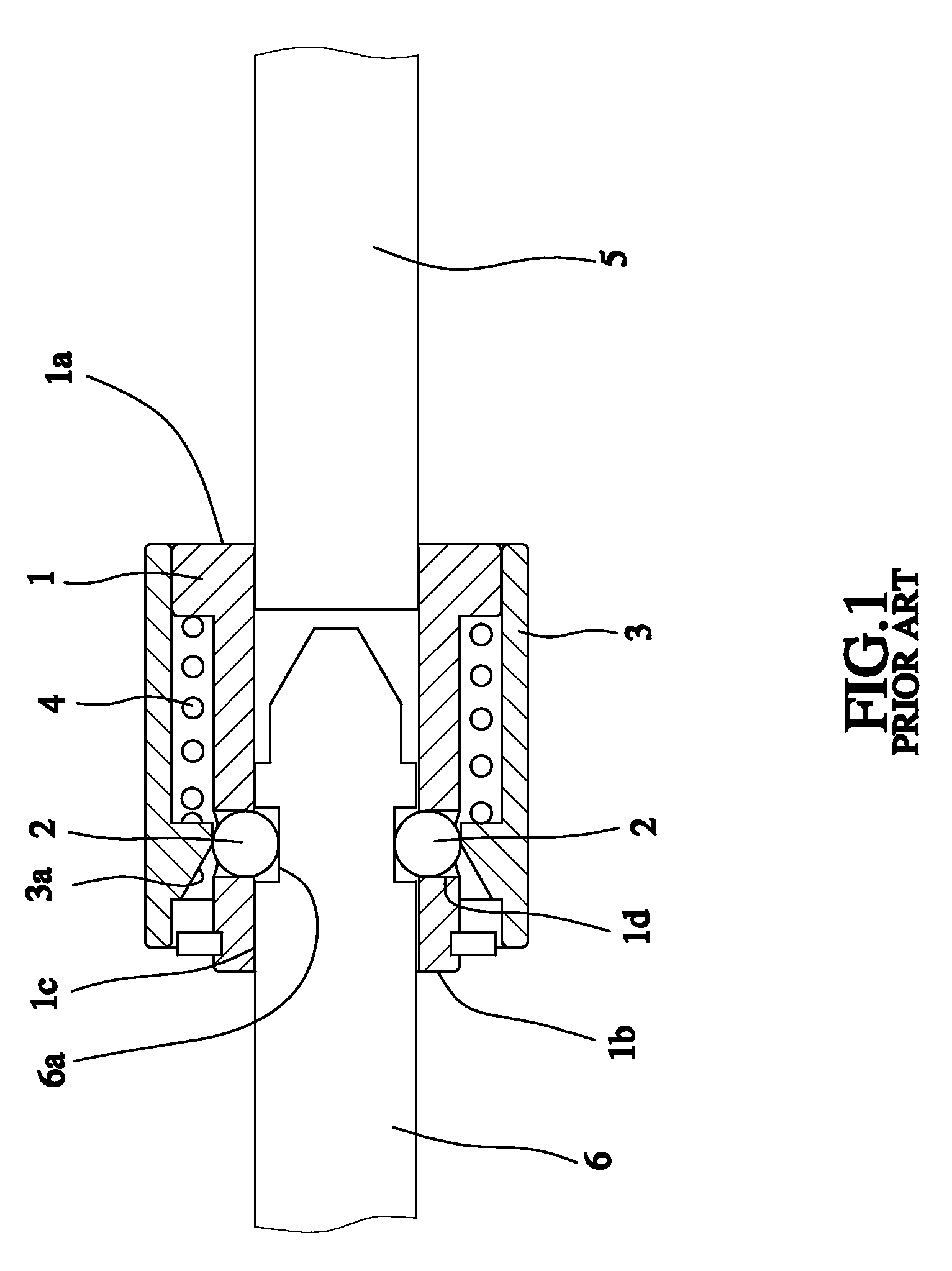
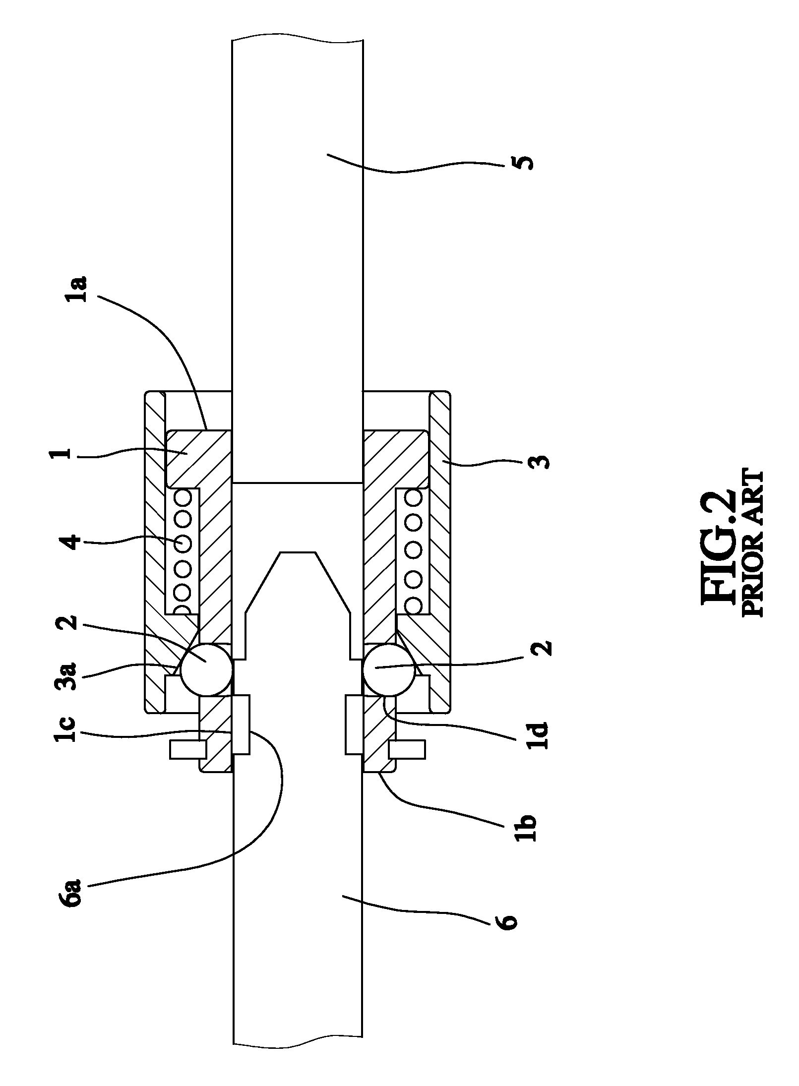
While replacing the cutter from the conventional cutter adapter, the user's hand must keep pressing the sleeve 3 to keep the sleeve 3 located at where the annular convex bevel 3a is away from the two steel balls 2, such that the user's hand is subject to ache and uncomfortableness to cause the operational inconvenience.
Besides, while replacing the cutter, the user not only keeps pressing the sleeve but also applies an axial stress to the drive shaft; if the drive shaft is not located at the top or bottom dead center of its moving path, removing the cutter will cause axial movement of the drive shaft to further potentially hurt the user.

Method used


Image

  • Cutter adapter for cutting machine
  • Cutter adapter for cutting machine
  • Cutter adapter for cutting machine

Examples


Embodiment Construction

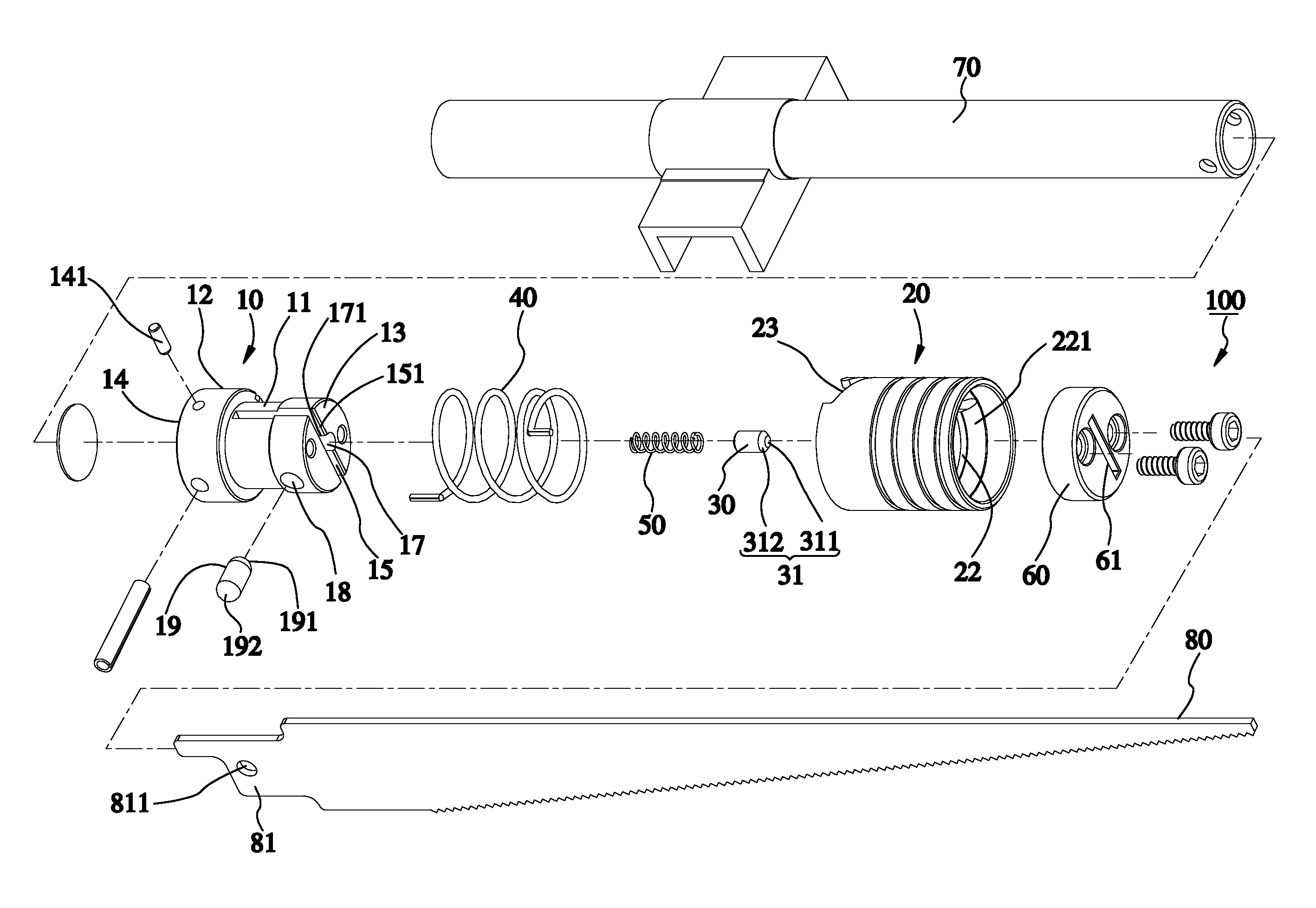
[0022]Referring to FIGS. 3 and 4, a cutter adapter 100 constructed according to a first preferred embodiment of the present invention is connected with a cutter 80 and a drive shaft 70 of a cutting machine. The cutter 80 includes a tang 81 having a lock hole 811 for the cutter adapter 100 to fasten the cutter 80. The cutter adapter 100 is composed of a holder 10, a lock pin 19, a sleeve 20, a biasing pin 30, a first spring 40, a second spring 50, and a limit cap 60, which are recited in the following respective paragraphs.

[0023]The holder 10 is column-shaped and includes a head portion 12 and a body portion 11 axially connected with the head portion 12. The head portion 12 has a larger external diameter than that of the body portion 11. The holder 10 includes a first end 13 and a second end 14. The first end 13 is the free end of the body portion 11. The second end 14 is the free end of the head portion 12 for connection with the drive shaft 70. The body portion 11 has a first recei...


PUM

PropertyMeasurementUnit
forcesaaaaaaaaaa
external diameteraaaaaaaaaa
internal diameteraaaaaaaaaa

Abstract

A cutter adapter includes a holder having a receiving portion for inserting a cutter therein; a sleeve sleeved onto the holder and having an annular bevel; a lock pin inserted into the holder and having an active end and a passive end, the passive end being squeezed by the annular bevel when the sleeve is moved, the active end being inserted into the cutter when the passive end is squeezed; and a biasing pin located in the receiving portion and pushed by a spring mounted in the receiving portion. In this way, when intending to mount the cutter to the cutter adapter, the user only needs to insert the cutter into the receiving portion to force the biasing pin to disengage from the lock pin, the lock pin being forced by the annular bevel to insert the active end into the receiving portion to hold the cutter.

Description

BACKGROUND OF THE INVENTION[0001]1. Field of the Invention[0002]The present invention relates generally to cutting machines, and more particularly, to a cutter adapter for a cutting machine.[0003]2. Description of the Related Art[0004]A general cutting machine includes a drive shaft capable of reciprocating motion. A cutter adapter is mounted to a free end of the drive shaft for mounting a cutter thereto. When the drive shaft is moved, the cutter is driven to cut a workpiece.[0005]Referring to FIGS. 1 and 2, a conventional cutter adapter is composed of a main body 1, two steel balls 2, a sleeve 3, and a spring 4. The main body 1 is column-shaped, having a first end 1a for connection with an output shaft of a cutting machine. The main body 1 includes a receiving tunnel 1c and two through holes 1d. The receiving tunnel 1c is provided with an opening formed at a second end 1b of the main body 1. The two through holes 1d are located at two lateral opposite sides of the receiving tunnel ...

Claims


Application Information

Patent Timeline
Patent Type & Authority Patents(United States)
IPC IPC(8): B27B11/06B23D51/08
CPCB23D51/10Y10T279/17717Y10T83/9481Y10T83/929
Inventor KUO, TUNG-CHIN
Owner MOBILETRON ELECTRONICS
Learn More