Airbag device

a technology of airbags and airbags, which is applied in the direction of pedestrian/occupant safety arrangements, vehicular safety arrangments, vehicle components, etc., can solve the problems of significant damage to the occupant, and achieve the effect of reducing the potential injury of the occupant by the deployed airbag, the direction of the deployment and the deployment speed of the airbag, and reducing the potential injury of the occupan

Active Publication Date: 2013-12-10
AUTOLIV DEV AB
View PDF5 Cites 2 Cited by
  • Summary
  • Abstract
  • Description
  • Claims
  • Application Information

AI Technical Summary

Benefits of technology

[0007]The present invention has been created with the foregoing in mind, and it is an object thereof to provide an airbag device that can reduce, while having a simple structure, the possible damage to the occupant caused by a deployed airbag.
[0009]According to the present invention having the above-described configuration, the deployment direction and deployment speed of the airbag can be controlled by the deployment restricting member, and potential injury to the occupant by the deployed airbag can be reduced. In particular, in a knee airbag device, a pressure applied close to the occupant's knees can be dispersed by initially deploying the upper portion of the airbag and then deploying, with a delay, the lower portion.

Problems solved by technology

However, according to the invention described in Japanese Patent Application Publication No. 10-315894, when the occupant is abnormally close to the instrument panel, the airbag may cause significant damage to the occupant.

Method used


Image

  • Airbag device
  • Airbag device
  • Airbag device

Examples


first embodiment

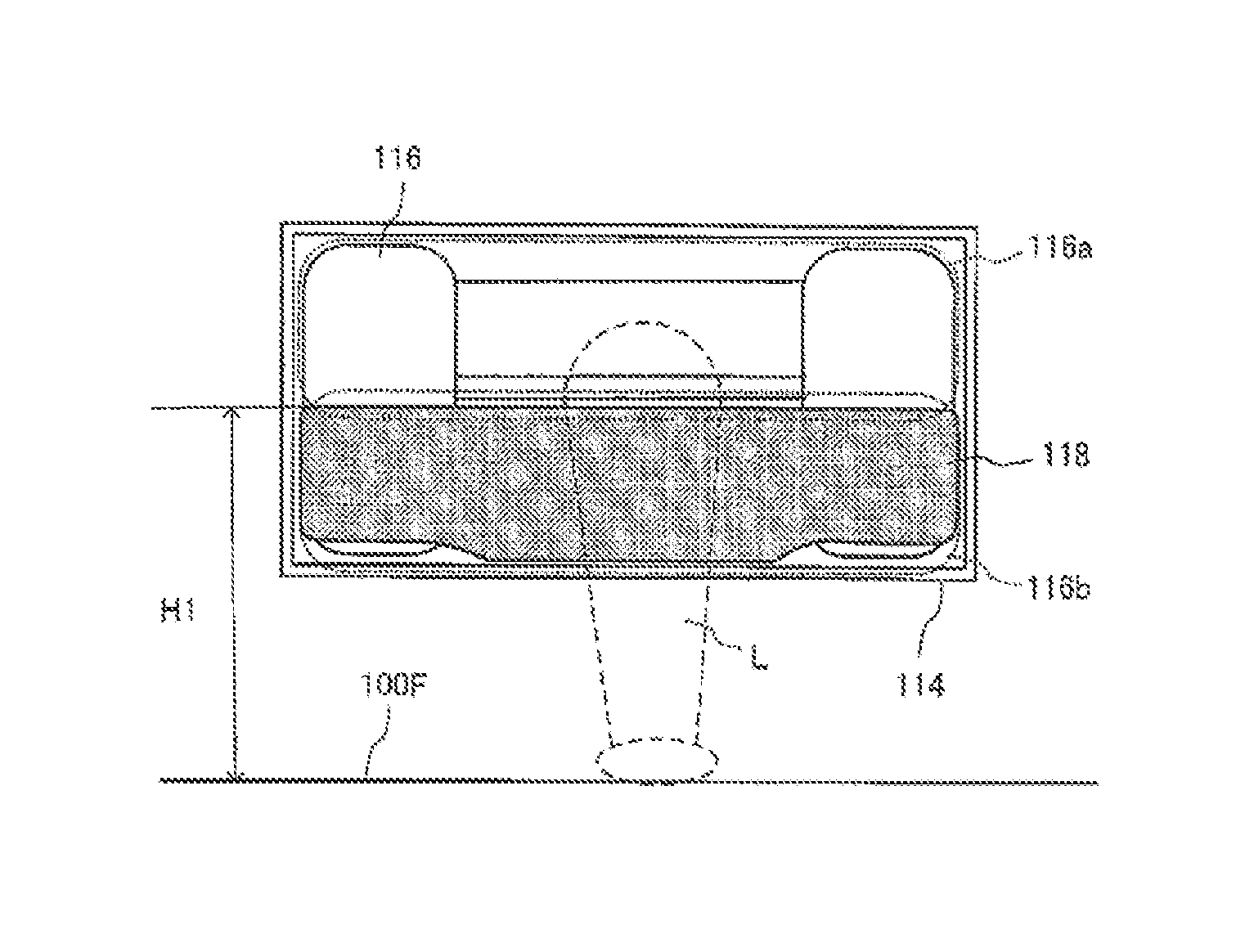
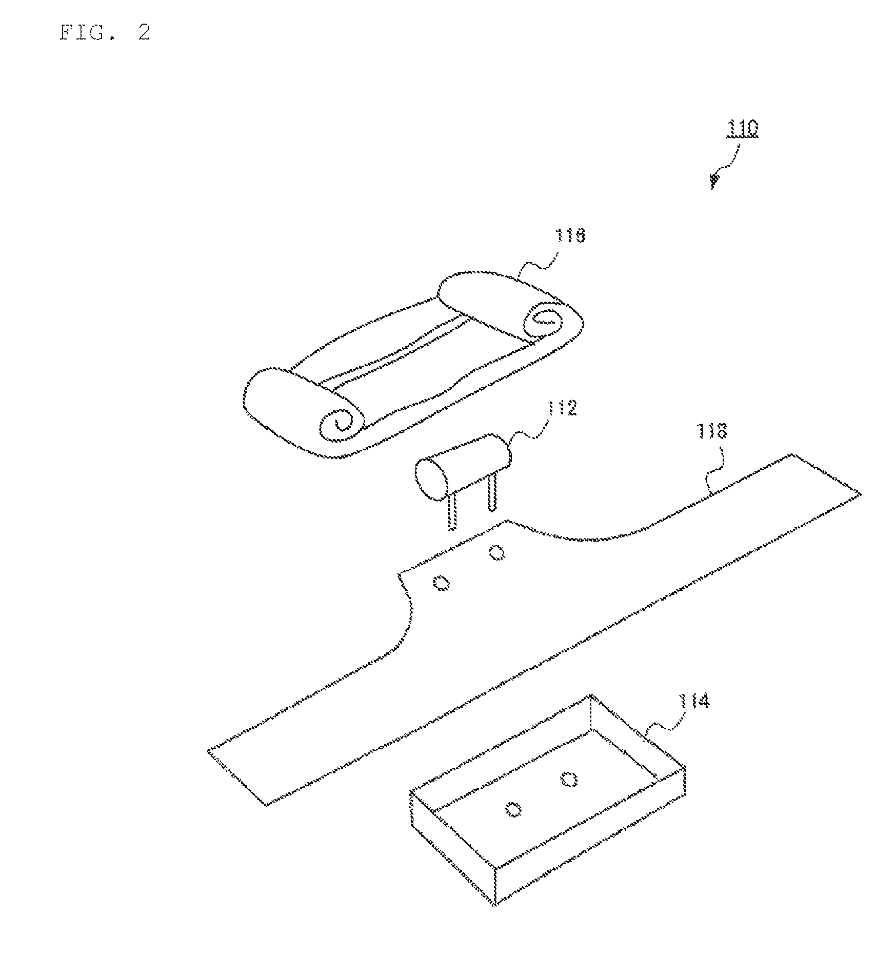
[0026]FIGS. 4(A) and 4(B) are views illustrating the process of assembling the knee airbag device 110 according to the The airbag 116 according to the present embodiment is initially wound or folded toward the center of the airbag 116 in the up-down direction (or front-rear direction), as shown in FIG. 4(A). Then, as shown in FIG. 4(B), the airbag is wound from the left and right or lateral ends toward the center of the airbag 116. In this case, when the airbag 116 accommodated inside the housing 114 is wound from the left and right sides, the airbag is not completely wound through the central portion. Rather, and the central portion is kept in an unwound state.

[0027]The lower portion of the folded airbag 116 is then enclosed with the restricting member 118. The state of the enclosed airbag 116 is shown in FIG. 3. When the airbag 116 is enclosed with the restricting member 118, one end of the restricting member 118 is fixed to the housing 114 and in this state the band-like portion...

second embodiment

[0035]The deployment restricting member 318 according to the present embodiment is provided with a base portion 334 that is fixed to a housing 314, a recess 332 forming a deployment non-restricted region of an airbag 316, and left and right side portions 336 covering the side surface of the airbag 316. The restricting member 318 is further provided with extension regions 338, between the recess 332 and the left and right side portions 336, that extend transverse to the side portions 336 and that are to be locked to hooks 314a of the housing 314. In the present embodiment, similarly to the above-described second embodiment, the roll portions positioned on the left and right sides of the folded airbag 316 are entirely enclosed by the side portions 336 and extension regions 338 of the deployment restricting member 318.

[0036]Locking holes 340 are formed at distal ends of the extension regions 338 of the restricting member 318, and these locking holes 340 engage with the hooks 314a of th...


PUM


Abstract

An airbag device having an airbag that can be inflated and deployed by inflating gas; a gas generator that supplies the inflating gas to the inside of the airbag; a housing that accommodates the airbag in a folded state; and a cloth-like deployment restricting member that is fixed at one end to the housing and that encloses part of the folded airbag. A deployment non-restricted portion of the airbag deploys upward, the deployment non-restricted portion not being enclosed by the deployment restricting member, and a deployment restricted portion, which is enclosed by the deployment restricting member, is deployed afterward.

Description

BACKGROUND[0001]1. Field of the Invention[0002]The present invention relates to an airbag device for installation on a vehicle. In particular, the present invention relates to an airbag device suitable for the so-called knee airbag aimed at protection of occupant's lower leg regions.[0003]2. Related Technology[0004]Vehicles such as automobiles are provided with an airbag system in which a bag is rapidly inflated by gas to prevent the occupants from colliding with dangerous zones, thereby minimizing or preventing injuries or death occurring when the occupant hits a hard part inside the vehicle, such as a steering wheel of front glass, during collision.[0005]When the vehicle collides, the occupant is moved forward by the inertia force and the occupant's knees strike against the instrument panel. In order to protect the occupant from such an impact, an airbag device that inflates from the lower surface of the instrument panel has been suggested.[0006]It is desirable that an airbag devi...

Claims


Application Information

Patent Timeline
Patent Type & Authority Patents(United States)
IPC IPC(8): B60R21/206B60R21/2334B60R21/2338
CPCB60R21/201B60R21/206B60R21/231B60R2021/161B60R2021/23169B60R2021/23386B60R21/20
Inventor OHSHINO, MASAKISHIMONO, HIROYOSHI
Owner AUTOLIV DEV AB
Why Eureka
Try Eureka