Agricultural implements with hinged and floating wings

a technology of agricultural implements and hinges, applied in the field of towed agricultural implements, can solve the problem of adding another degree of limited freedom to the machine, and achieve the effect of simple hinge design

Active Publication Date: 2012-02-21
LANDOLL
View PDF34 Cites 18 Cited by
  • Summary
  • Abstract
  • Description
  • Claims
  • Application Information

AI Technical Summary

Benefits of technology

[0010]More specifically, the hinge between each wing and the center section includes a ball joint adjacent one end of the hinge, and a guide roller in a roller slot adjacent the other end of the hinge. Certain components of the hinge, i.e., the ball of the ball joint and the roller slot, are non-rotationally and fixedly attached to the center section. The hinge axis extends substantially in a longitudinal direction from front to rear of the center section and passes through the ball joint and the guide roller The terms “longitudinal” and “longitudinal hinge axis” as used herein are intended to include a few degrees variation sideways from true longitudinal to allow folding of the wings without interfering with each other as shown in FIG. 2; as well as a few degrees up and down from true longitudinal as the guide roller moves up or down in the guide roller slot. The ball joint and the roller in the roller slot allow the wing to be folded up over the center section. Further, the ball joint and guide roller in roller slot allow a floating action of the wing about a further “float” axis perpendicular to the hinge axis to a degree determined by the depth of the roller slot. The hinge pin and hinge plates / barrels of the conventionally hinged pulverizer are eliminated. The floating action provided prevents the undesirable weight transfer from the wing sections to the center section and vice versa, through the designated range of floating provided by the new hinge design. The pulverizer thus is now able to conform to the contour of the soil to ensure that uniform conditioning takes place across the entire width of the machine. A further feature of the design is that if an obstacle such as a stone is encountered while in use, the section that rolls over the stone does not affect the rest of the machine since there is no weight transfer between sections.
[0011]It should also be noted that the new hinge design allows the pulverizer to be backed up in a field without the wings interfering when in the operating position.

Problems solved by technology

However, another degree of limited freedom is added to the machine to apply a limited floating action to the wings.

Method used


Image

  • Agricultural implements with hinged and floating wings
  • Agricultural implements with hinged and floating wings
  • Agricultural implements with hinged and floating wings

Examples


Embodiment Construction

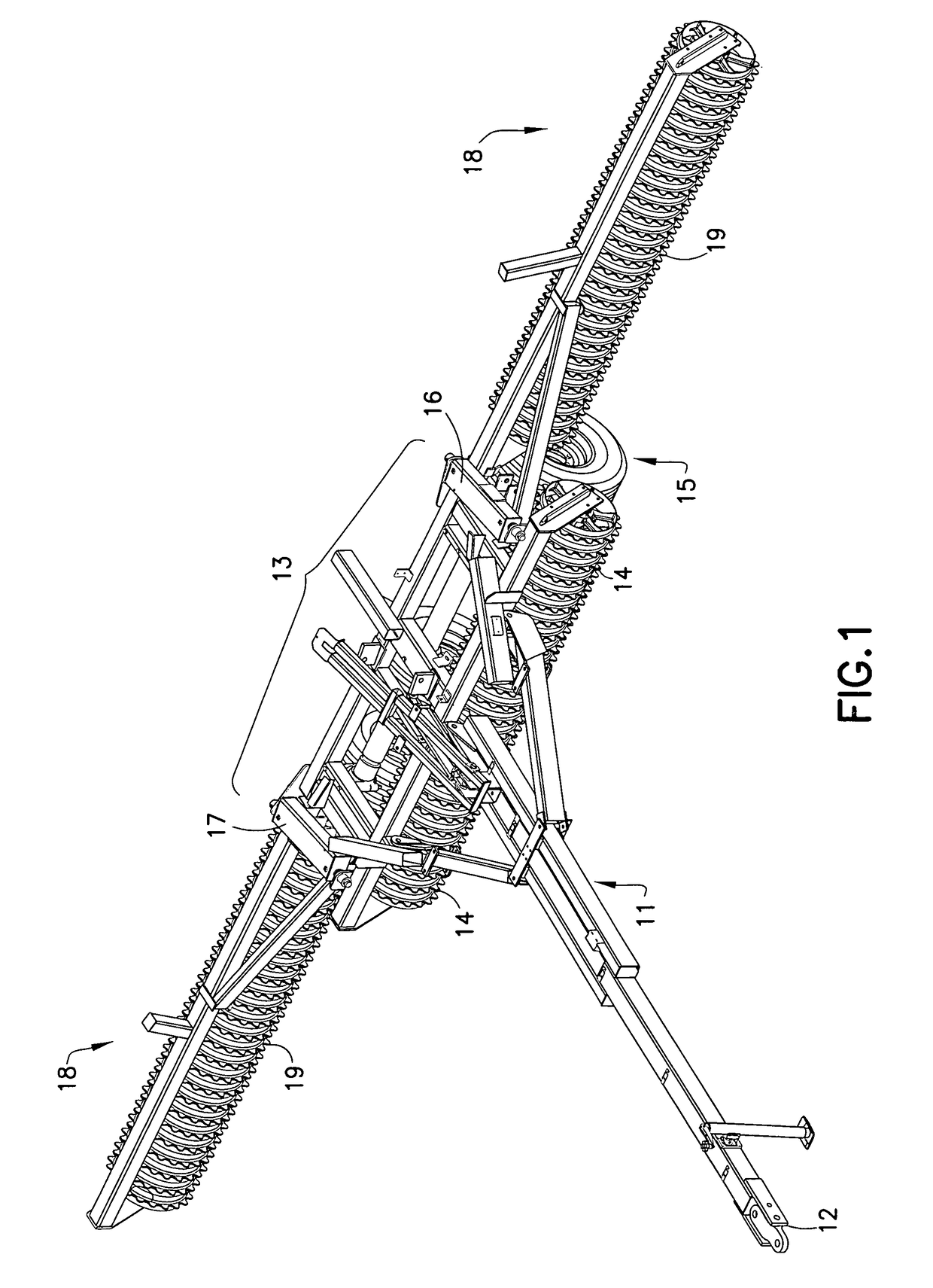
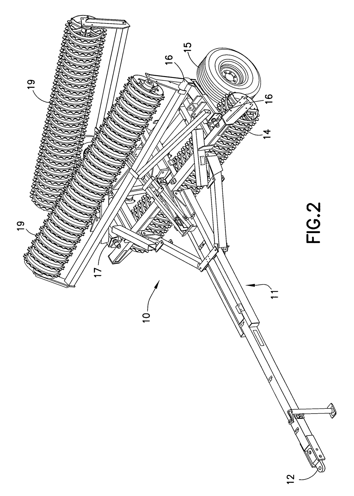
[0026]Referring to FIG. 7, the pulverizer 30 is shown assembled with drawbar 31 for towing center section frame 32 having forwardly positioned center section rollers 33, wings 34 and 35 with wing rollers 36 and the wings being unfolded and extended on opposite sides of center section 32, the transport wheels and axle and rockshaft assembly 37, and the new hinge joints 38 and 39. FIG. 8 illustrates the enlarged and exploded hinge joint 39 positioned on the side of the center section as shown in FIG. 7, there being a corresponding hinge joint 38 present on the opposite side of center section 32 to connect wing 35. The following discussion, therefore, correspondingly applies to hinge joint 38 as well.

[0027]Referring to FIG. 8, new hinge joint 39 is comprised of roller slot 50 which is part of center section 32 at the outside rear of that section, guide roller 51 attached to wing 34 at its inner rear portion for mounting in roller slot 50 for up and down motion therein, ball joint ball ...


PUM


Abstract

A towable soil pulverizer having a longitudinal center section, and foldable wings mounted by hinges on opposite sides of the center section to fold upwardly or downwardly about substantially longitudinal hinge axes. The wings and center section have ground working rollers. Each hinge has a spaced ball joint and guide roller in roller slot. A wing float axis for each wing extends substantially perpendicular to the longitudinal hinge axis in a transverse direction, each wing also being pivotal about the float axis. The hinge design with the float axis prevents weight transfer between the center section and wing sections when the pulverizer operates over uneven soil, to provide uniform soil conditioning over the width of the pulverizer. The center section rollers are positioned ahead of (or behind or co-linear with) the wing rollers. Components of the ball joint and roller guide in slot are fixedly and non-rotationally attached to the center section.

Description

FIELD OF THE INVENTION[0001]The present invention relates to towable agricultural implements such as soil pulverizers which have a center section and foldable wing sections mounted on opposite sides of the center section. The wings are unfolded when working the ground and are folded when transporting the pulverizer between fields or elsewhere.BACKGROUND OF THE INVENTION[0002]Pulverizers are used by farmers during planting season to help prepare an ideal seedbed. Since yield is a direct result of germination, which is dependent on soil conditions at planting time, having an ideal seedbed is desired. Pulverizers break up clods and insure good seed to soil contact, reducing germination time. Since the seedbed is firmed and air pockets are eliminated, capillary action in the soil is also increased making more moisture available to the plant through its root.[0003]As fields become larger and individual farms cover more acres, equipment has become larger to cover more land in less time. O...

Claims


Application Information

Patent Timeline
Patent Type & Authority Patents(United States)
IPC IPC(8): A01B63/00
CPCA01B29/041A01B73/044
Inventor TAMM, CHRISTOPHER LEEREICHARDT, NORMAN GEORGE
Owner LANDOLL
Why Eureka
Try Eureka