
Multi-axis cylinder manipulator

a multi-axis, manipulator technology, applied in the direction of machine supports, manufacturing tools, applications, etc., can solve the problems of time-consuming and cumbersome repositioning of rockets with cranes, and the absence of linear translation of existing carts

Inactive Publication Date: 2012-02-21
THE UNITED STATES OF AMERICA AS REPRESENTED BY THE SECRETARY OF THE NAVY
View PDF15 Cites 29 Cited by
  • Summary
  • Abstract
  • Description
  • Claims
  • Application Information

AI Technical Summary

Benefits of technology

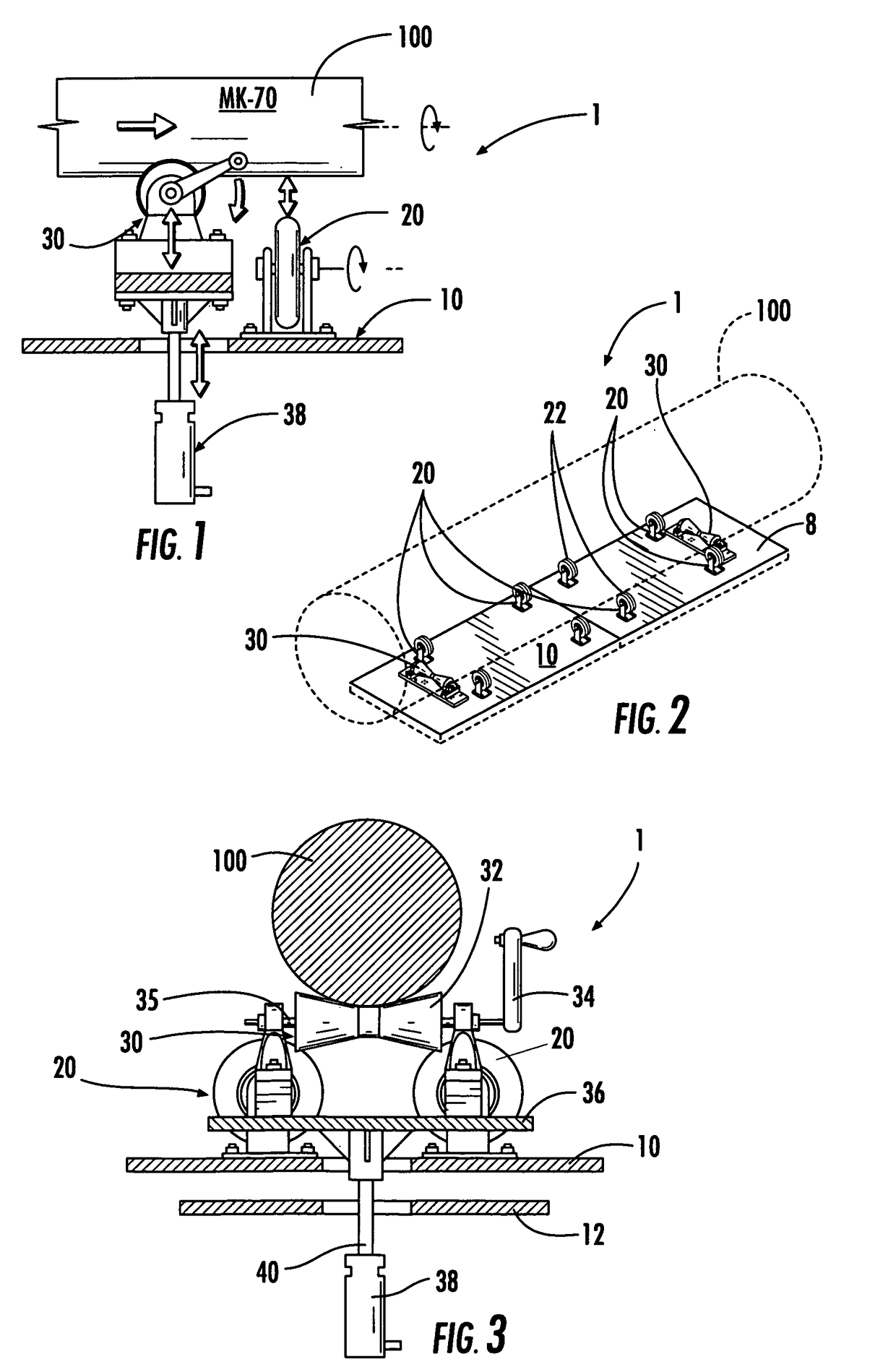
[0009]Multi-axis movement is accomplished by two sets of rollers: rotational and translational. The translational roller set is held in a retracted and unengaged position while the cylinder rests on the rotational roller set. Movement about the axis of the rotational roller set is allowed in this position. The translational roller set may, at anytime, be engaged with the cylinder, disengaging the cylinder from the rotational roller set. When this action occurs, movement about the axis of the rotational roller set is not allowed, but translational movement is allowed. Accordingly, the cylinder is moved to the desired position by either pushing on the cylinder or cranking the translational roller. The action may be reversed to once again, allow movement about the axis of the rotational roller set. The process may be repeated as needed. The rollers or the cylinder may be powered by motor or manual device.

Problems solved by technology

Currently existing carts do not have a means of linear translation, and therefore an overhead crane is used to reposition the rocket.
Repositioning the rocket with a crane is time consuming and cumbersome.

Method used


Image

  • Multi-axis cylinder manipulator
  • Multi-axis cylinder manipulator
  • Multi-axis cylinder manipulator

Examples


Embodiment Construction

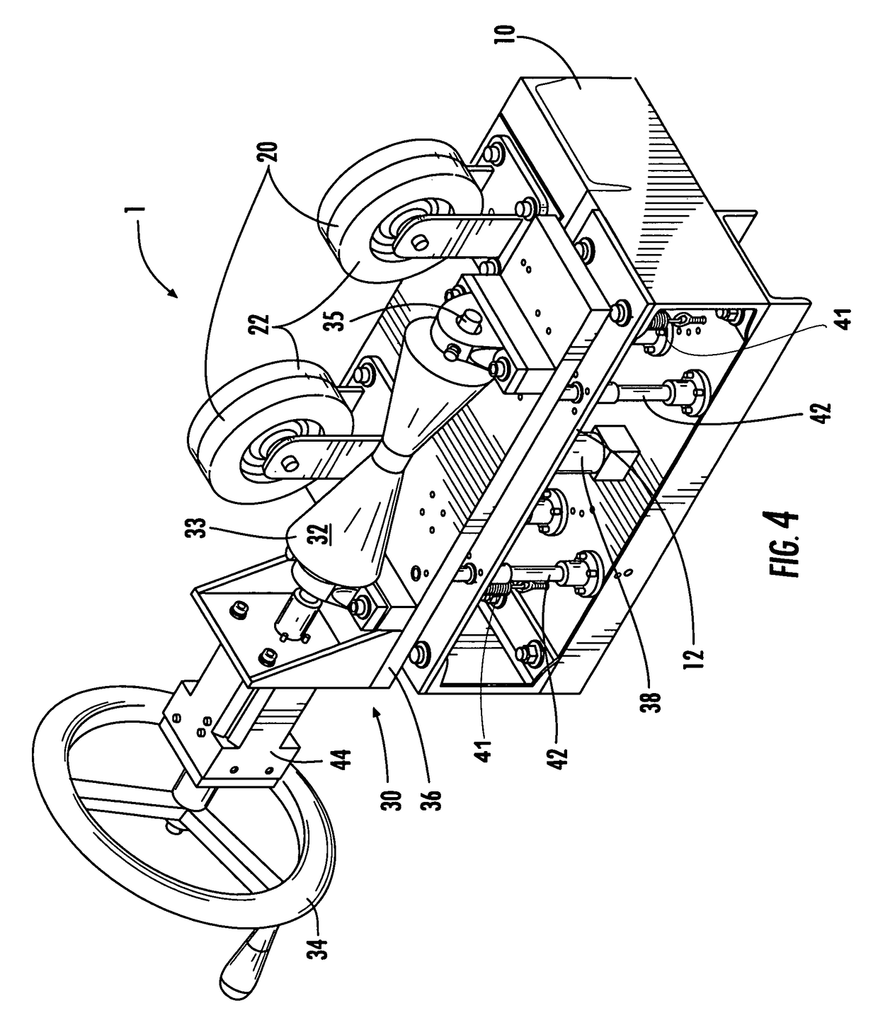
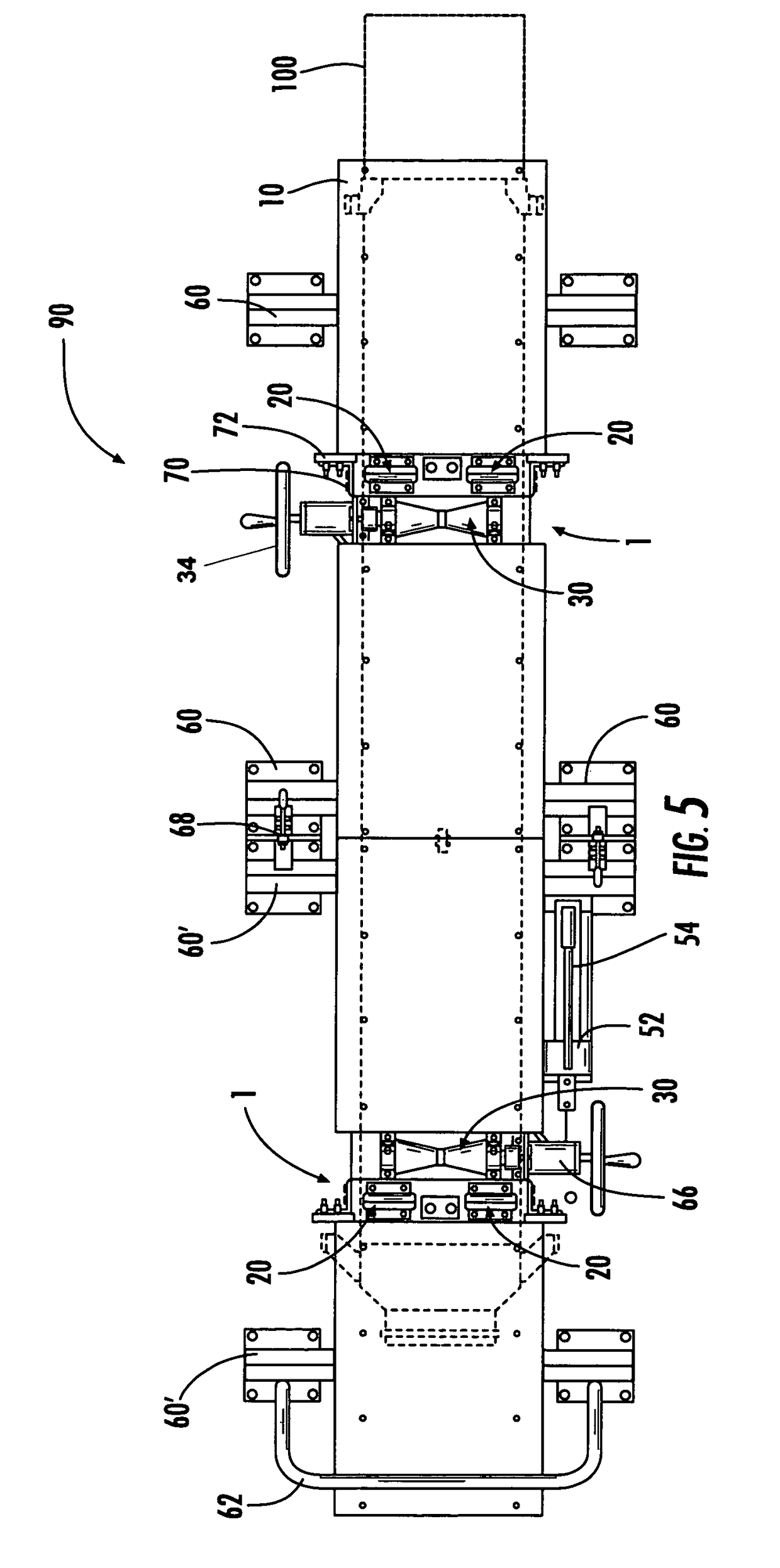
[0017]An embodiment of the invention is shown and described in the attached drawings, where the invention includes a multi-axis cylinder manipulator apparatus, a cart or coupled carts forming a unified cart having the invented apparatus, and a method for utilizing the a multi-axis cylinder manipulator apparatus.

[0018]Referring to FIGS. 1, 2 and 3, the multi-axis cylinder manipulator apparatus 1 is mounted on a structurally rigid frame 10 having a top-side, a bottom side, and a plurality of lateral sides, where the frame has a length, a width and a thickness, and generally has a plurality of reinforcing elements 12. There is a set of rotational rollers 20 mounted on the top-side of the frame 10, where said rotational rollers have a sufficient hardness durometer, number of rollers, diameter, footprint width, positioning and ease of rotation to non-abrasively support a filled cylinder 100, such as a rocket motor MK-70. The cylinder 100 is held horizontally at a height above the frame 1...


PUM

PropertyMeasurementUnit
diameteraaaaaaaaaa
lengthaaaaaaaaaa
widthaaaaaaaaaa

Abstract

An apparatus and method for both rotating a cylinder about its center axis and translating the cylinder linearly along the same axis. The invention is suitable for X-raying rockets and other cylindrical objects. Multi-axis movement is accomplished by two sets of rollers: rotational and translational. The translational roller set is held in a retracted and unengaged position while the cylinder rests on the rotational roller set. Movement about the axis of the rotational roller set is allowed. When the translational roller set is engaged with the cylinder, the cylinder is disengaged from the rotational roller set, and movement about the axis is not allowed, but linear movement is allowed. The action may be reversed and repeated. The rollers or the cylinder may be powered by motor or manual device.

Description

STATEMENT OF GOVERNMENT INTEREST[0001]The invention described herein may be manufactured and used by or for the Government of the United States of America for Governmental purposes without the payment of any royalties thereon or therefore.BACKGROUND OF THE INVENTION[0002]1. Field of the Invention[0003]The invention relates generally to a conveying apparatus, and more particularly to a cart that enables both rotating a cylinder about its center axis and translating the cylinder linearly along the same axis.[0004]2. Prior Art[0005]Carts used to convey objects that are to be X-rayed, where the object is typically cylindrical in shape, have a mechanism that allows the object to be rotated, but require that the object be repositioned several times to obtain a complete set of X-rays, where there are no areas obstructed by the cart. In the case of rockets, the rocket requires linear translation in order to perform X-ray scans free of obstructed areas created by the rotational rollers. Scan...

Claims


Application Information

Patent Timeline
Patent Type & Authority Patents(United States)
IPC IPC(8): B23Q3/00B23Q3/18B25B1/00B25B27/14B21G7/08A47F5/12B25H1/00
CPCB23Q7/05F41A9/87F42B35/00B62B3/104Y10T29/16B62B2202/022B62B2203/74Y10T29/53961
Inventor BARGER, BRIAN BLAIR
Owner THE UNITED STATES OF AMERICA AS REPRESENTED BY THE SECRETARY OF THE NAVY
Learn More