Closure and dispensing system

a technology of dispensing system and container, which is applied in the field of dispensing system, can solve the problems of membrane rupture or perforation, and achieve the effect of convenient dispensing of container contents and simple us

Inactive Publication Date: 2012-02-28
BAKER RAYMOND J
View PDF22 Cites 18 Cited by
  • Summary
  • Abstract
  • Description
  • Claims
  • Application Information

AI Technical Summary

Benefits of technology

[0019]Preferably, the shape of the boss corresponds substantially to the cavity so that walls of the cavity closely engage the outer surface of the boss. In one form, one or both of the cooperating surfaces is / are formed with ribs or other formations, or barbs or the like to assist inter engagement of the boss within the cavity and to assist in maintaining the boss in the engaged position to minimise the possibility of accidental removal of the boss from the cavity during withdrawal of fluid from the container.
[0022]In preferred embodiments, the boss has a portion that passes through the duct so that the dispensing device communicates directly with the interior of the container. When the boss is withdrawn, the duct closes to again seal the container interior. The hollow opening through the boss may be of a size that relatively viscous liquids may be easily withdrawn from the container.
[0023]In one form, the dispensing device is in the form of a syringe barrel having a plunger to create the pressure differential. Preferably, after extraction of fluid from the container using the syringe, the syringe is withdrawn from the container closure and is then used to dispense the fluid either directly through the syringe outlet or through a needle attached thereto. A syringe for use with embodiments of the invention may be of any size commensurate with the container contents and the intended use thereof. Small, precise measurements of small quantities of fluid may be made with a small syringe while large amounts of fluid may be extracted and quickly and easily dispensed using a large syringe.

Problems solved by technology

Thus, in the latter case, fluid pressure applied to the membrane on one side thereof may cause the membrane to rupture or perforate to allow the fluid to pass therethrough.

Method used


Image

  • Closure and dispensing system
  • Closure and dispensing system
  • Closure and dispensing system

Examples


Embodiment Construction

[0027]In order that the invention is more readily understood, embodiments thereof will now be described with reference to the accompanying figures and legend:

[0028]

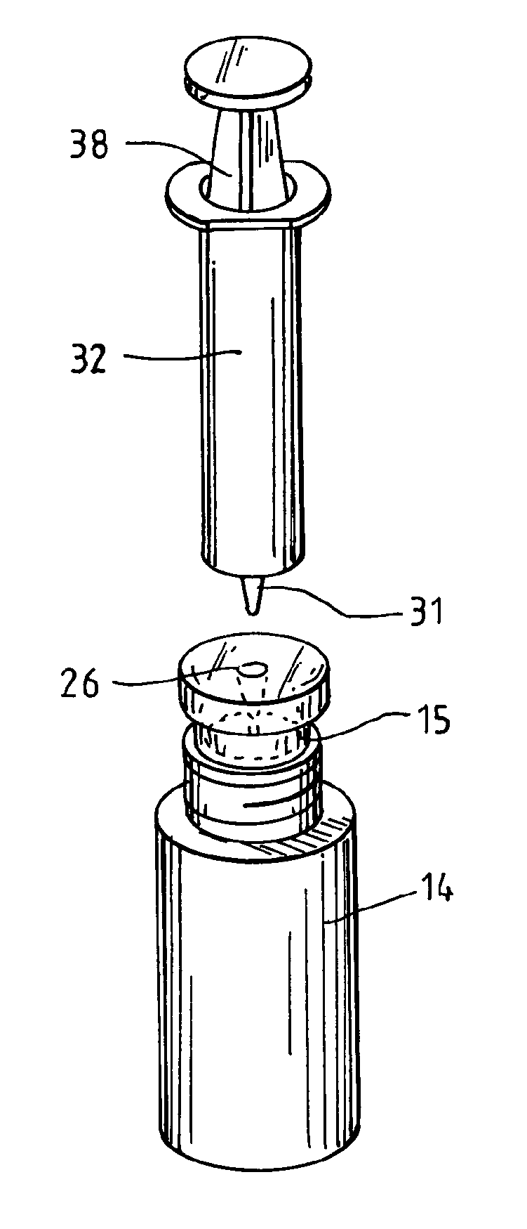
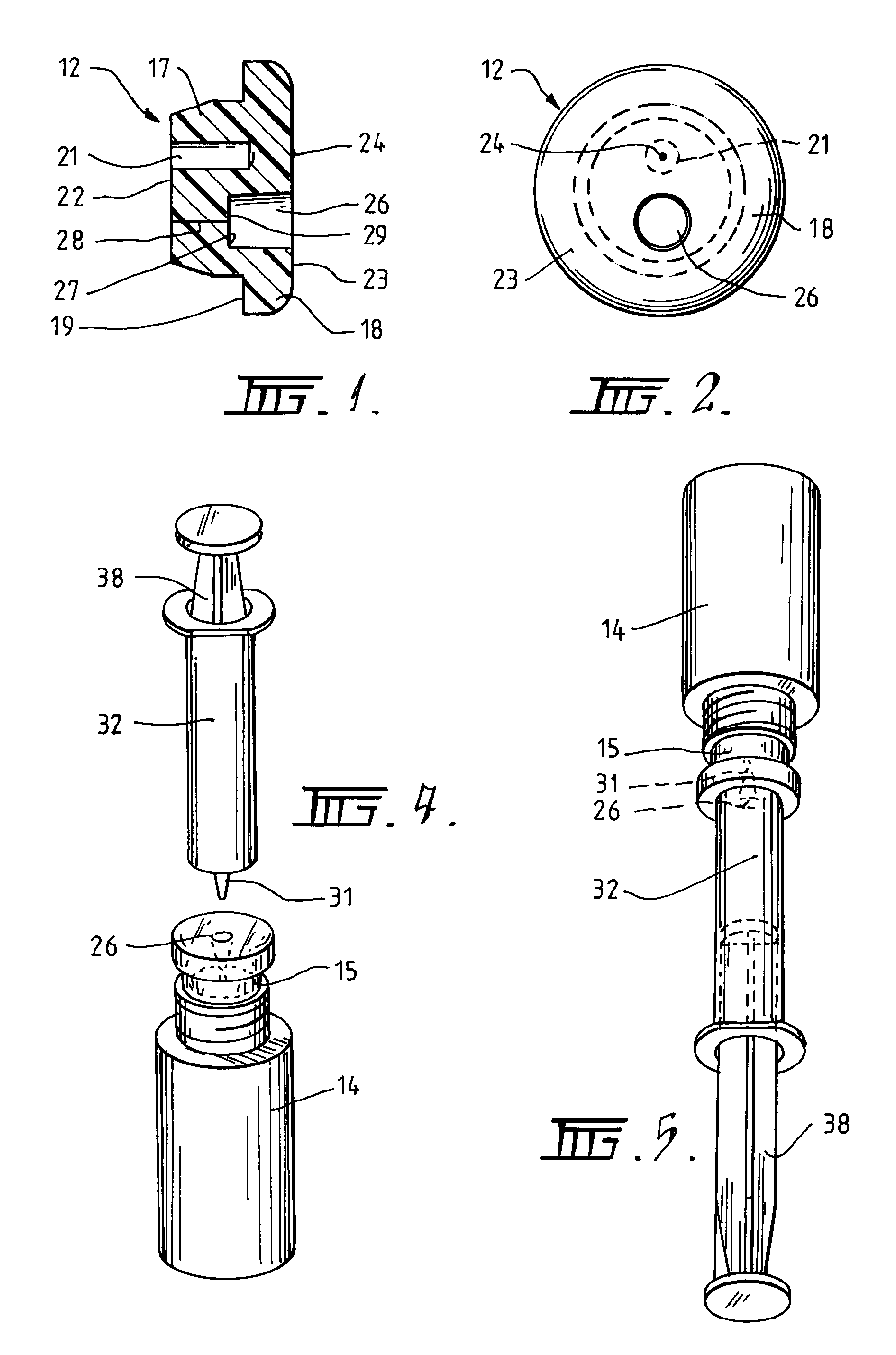
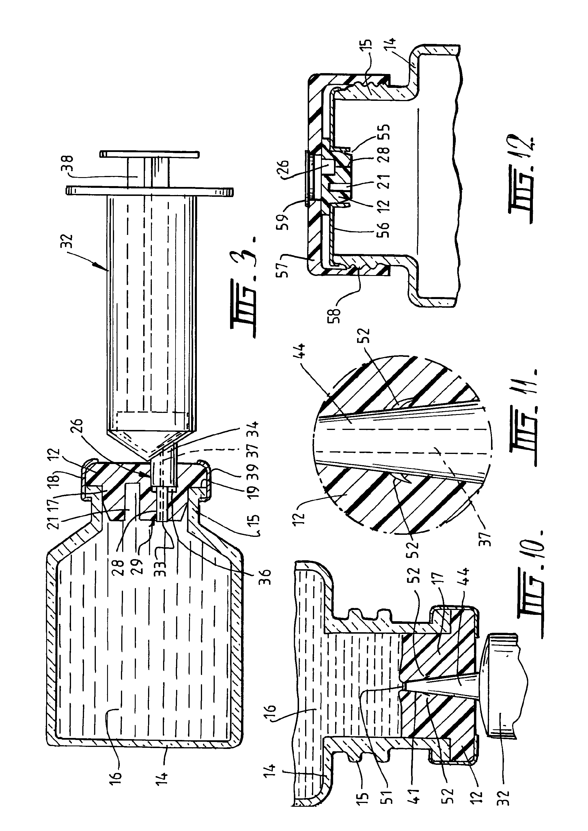
Legend12.Closure14.Container15.Neck16.Fluid17.Body18.Head19.Surface21.Opening22.Lower surface23.Outer surface24.Indentation26.Recess / Cavity27.Inner surface28.Duct29.Sealing membrane31.Boss32.Syringe33.Outer part34.Inner part36.Shoulder37.Channel38.Plunger39.Tamper ring41.First blind opening42.Second blind opening43.Membrane44.Conical boss46.Barrel47.Slit or hole in membrane51.Web52.Barbs55.Opening56.Bridging cap57.Sealing top58.Threads59.Disc

[0029]FIG. 1 is a cross sectional, elevational view of a closure in accordance with one embodiment of the invention;

[0030]FIG. 2 is an end elevational view of the closure of FIG. 1;

[0031]FIG. 3 is a cross sectional view of the closure of FIG. 1 secured to a vial and having a syringe engaged therewith;

[0032]FIG. 4 is a perspective view of a second embodiment of the invention;

[0033]FIG....


PUM

PropertyMeasurementUnit
shapeaaaaaaaaaa
pressureaaaaaaaaaa
thicknessaaaaaaaaaa

Abstract

A closure (12) for a container (14) adapted to store fluid (16) to be dispensed, said closure comprising a body (17) having an outer surface (23) communicating with the exterior of said container and an inner surface (27) embedded within said body wherein said outer surface includes a cavity (26) adapted to sealably receive a dispensing device (32).

Description

CROSS-REFERENCE TO RELATED APPLICATIONS[0001]The present application claims priority from Australian Provisional Patent Application No 2006906330 filed on 13 Nov. 2006, the content of which is incorporated herein by reference.INTRODUCTION TO THE INVENTION[0002]This invention relates to a closure for a fluid container which facilitates dispensing the fluid. The invention also relates to a dispensing system for dispensing a fluid stored in a container.[0003]The invention is particularly suitable for dispensing liquids, slurries, lotions, creams and other similar substances. The system may also be adapted to dispense gases, if required. However, for ease of understanding, the invention will be described herein in relation to the dispensing of a liquid substance stored in a container.BACKGROUND TO THE INVENTION[0004]Many liquid substances, including pharmaceutical and veterinary preparations, substances for medical use, chemical reagents and numerous other substances need to be dispense...

Claims


Application Information

Patent Timeline
Patent Type & Authority Patents(United States)
IPC IPC(8): B65B1/04
CPCB65D51/002
Inventor BAKER, RAYMOND J.
Owner BAKER RAYMOND J
Why Eureka
Try Eureka