Sealing device

a sealing device and sealing wire technology, applied in the direction of heating elements, electric/magnetic/electromagnetic heating, manufacturing tools, etc., can solve the problems of difficult maintenance (e.g., heater wire replacement) and high cost, and achieve the effect of avoiding winding and breakage after a few revolutions

Inactive Publication Date: 2012-02-28
PREGIS INTELLIPACK CORP
View PDF92 Cites 16 Cited by
  • Summary
  • Abstract
  • Description
  • Claims
  • Application Information

AI Technical Summary

Benefits of technology

[0019]The present invention is directed at problem reduction relative to prior art sealers such as the edge sealers described above, by avoiding, for example, some of the complexities associated with the coil wire wrap arrangement like that in the above noted '208 patent and avoiding the often replacement requirement of the above noted '638 patent embodiment. A preferred embodiment also avoids the need for a tape cover or the like (e.g., cover means used to avoid film cutting in a sealing operation not involving cutting).
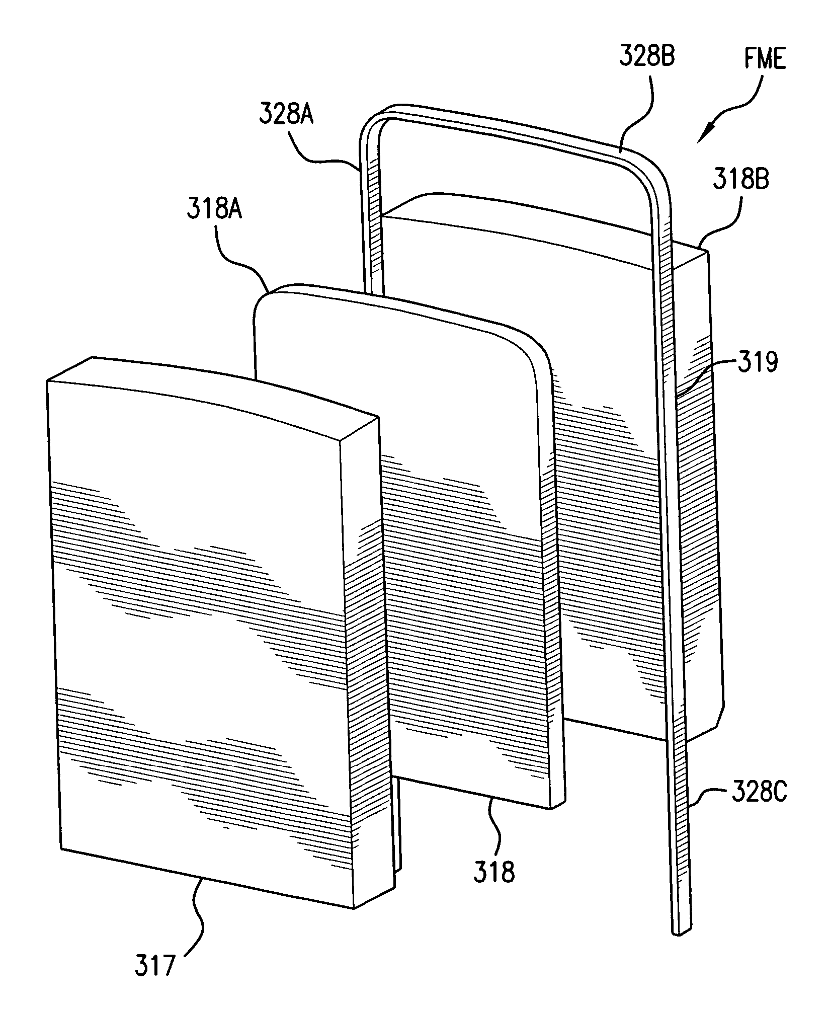
[0021]The edge sealer is well suited for use in a foam-in-bag assembly that comprises a film feed mechanism which feeds film with a film driver, a bag forming assembly which includes the edge sealer that, in a preferred embodiment, directly contacts film being fed by the film driver and which is preferably supported on a fixed (or repetitious repeat) position relative to the foam-in-bag assembly. In this way there can be maintained a desired film to heater element sealing engagement (direct contact preferred although the subject matter of the present invention is inclusive of a non-direct contact relationship but one where the heater element is close enough to effect seal formation although a direct contact, “tapeless” embodiment is preferable). A preferred embodiment also features a common plane “flush” relationship wherein a flat surface of the heater element is co-planar with the substrate's film contact surface or surfaces so that the facing surface of the heater element contacts the film at the same time as the film contacts the substrate's film contact surface(s). The edge sealer also preferably presents an essentially solid surface below the flush plane and relative to the heating element as in a rectangular heating element having received within the substrate without side gaps and any adjacent substrate component(s) avoiding side gaps in the region of the film where there is a possibility of melted film generation.
[0025]Relative to the “earlier inventive edge sealer embodiments” (and also many prior art devices), the tape covering (e.g., Kapton™ tape material) covering the seal wire and the insert has to be replaced frequently, to maintain seal quality, and to prevent what is known in the art as “ribbon-cutting”. Ribbon-cutting occurs when the seal wire slices the outside edge away from the body of the bag, essentially forming a ribbon of film that is no longer a part of the bag itself. Ribbon-cutting occurs when the tape covering over the seal wire wears away, exposing the round wire edge to the film. The exposed wire becomes like a hot knife that cuts the film rather than creating the desired seal. Seal quality is not very good when the edge sealer is ribbon-cutting. The seals are weak, and can break under slight pressure, such as that generated from rising foam inside of a bag being manufactured by a foam-in-bag assembly, by the air pressure involved in an “air-in-bag” assembly or internal pressure involved with a “food-in-bag” assembly. In some of the earlier inventive edge sealer embodiments, tape replacement is required, on every film roll change, if not more often. Also, in an effort to maintain optimum seal quality and avoid the problems associated with ribbon-cutting, recommended tape replacement for the tape over the seal wire is every 700 to 1000 bags, which usually means multiple tape replacements per film roll. Other tape material options have been explored, other than KAPTON™ material, and the inventors have found that KAPTON™ material provides a good compromise taking into account the elements associated with well functioning tape material and successful high resistance to abrasion and heat. The avoidance of having to use any tape material is preferred under the present invention in any event.
[0032]Acetal is inexpensive and easy to machine, but it is not as rigid or as strong as metals like steel or aluminum. Consequently, the arbor bodies of some earlier inventive edge sealer embodiments were somewhat flexible, and would bend slightly under stress. This bending can exacerbate the electrical connection issues outlined in the above section, so that edge sealers can become intermittent or simply stop working altogether when subjected to normal handling or installation stresses. Often, the effective electrical resistance of the edge sealer assembly is increased due to this flexing problem, because of shifts in the contact point between the seal wire on the face of the contact blocks. When this happens, the seal wire length is essentially lengthened, because its point of connection with the contact block will move further down the face of the arbor. In this situation, the edge sealer may continue to function, but the operator may have to adjust the heat setting in software because of the higher resistance value.
[0040]The earlier inventive edge sealer embodiments presented some difficulties in assembly into a working unit. The arbor body on the earlier inventive edge sealer embodiments included ones made of Acetal. However, the Acetal body is not very rigid, so it will bend significantly as the diagonal screws were tightened into the contact blocks of a preferred design. This bending tends to pull the contact blocks away from the VESPEl insert, and also away from contact with the seal wire, thus increasing the resistance of the edge sealer. At times, the bending of the body is enough to completely open the circuit, or the body may bend sufficiently to make the housing or arbor body of the edge sealer difficult to install in its base support. This is typically due to the plugs that extend from the bottom of the arbor body in a preferred embodiment become unparallel, and they no longer line up with their mating sockets in the base support, which are parallel. The assembler has to be very careful to not over tighten the screws, but if the screws are not tight enough, that can cause poor contact and erratic resistance. If the screws are too tight, the arbor body can be distorted so that its conductor plugs (e.g., Multilam) plugs will not fit into the pair of mating sockets in its base on the machine.

Problems solved by technology

A problem associated with the '208 patent approach is that it requires a rotating electrical contact to supply power to the edge seal wire.
Since the edge seal wire is rotating with the nip roll, direct wire connections from the edge seal wire to the non-rotating control board presents the potential for wind up and breakage after a few revolutions.
This problem is addressed with a rotating electrical union, which is quite expensive and has many failure modes of its own.
Also, maintenance (e.g., heater wire replacement) is difficult with this embodiment as can be seen by the high finger dexterity requirement associated with removing and replacing wires on its substrates.
In addition, even with a highly skilled person with good dexterity the switching out of a defective wire for a new one is time consuming and thus also undesirable to a user from a manufacturing “down time” efficiency standpoint.
A disadvantage of this commercialized embodiment of the '638 design is its short life in comparison to other designs.
A further difficulty associated with the prior art designs is seen in the difficulty of forming and maintaining good seal production as opposed to weak or defective seals due to improper bonding temperature or surface contact, or too much contact or heat application and a resultant improper ribbon cutting (in situations where ribbon cutting is not an intended result).
1. The seal wire melts into the substrate, as in “Acetal” or “Delrin” material, causing it to lose sealing power into the substrate, leading to poor seals.
2. The seal wire burns a hole in the Teflon tape that covers it, causing the unit to make bad seals.
3. In general, seal quality is not consistent, causing the machine operator to make frequent adjustments to the temperature settings or attempts to repair the edge seal card in order to maintain seal quality.
4. The edge seal cards are not interchangeable, and the machine operator has to adjust its temperature setting every time a new one is installed.
5. When the 10-mil Nichrome wire does fail there is no easy way to replace it, which is frustrating to operators because the wire only costs a few cents while the entire card assembly is much more expensive.
6. The rubber roll will gradually wear a matching radius into the edge of the plastic edge seal card in contact with it, reducing its usefulness over time.
7. The cables that connect the edge seal card to the plug-in connector panel, frequently get caught in the nip rolls or in the sealing jaws.

Method used


Image

  • Sealing device
  • Sealing device
  • Sealing device

Examples


embodiment 91

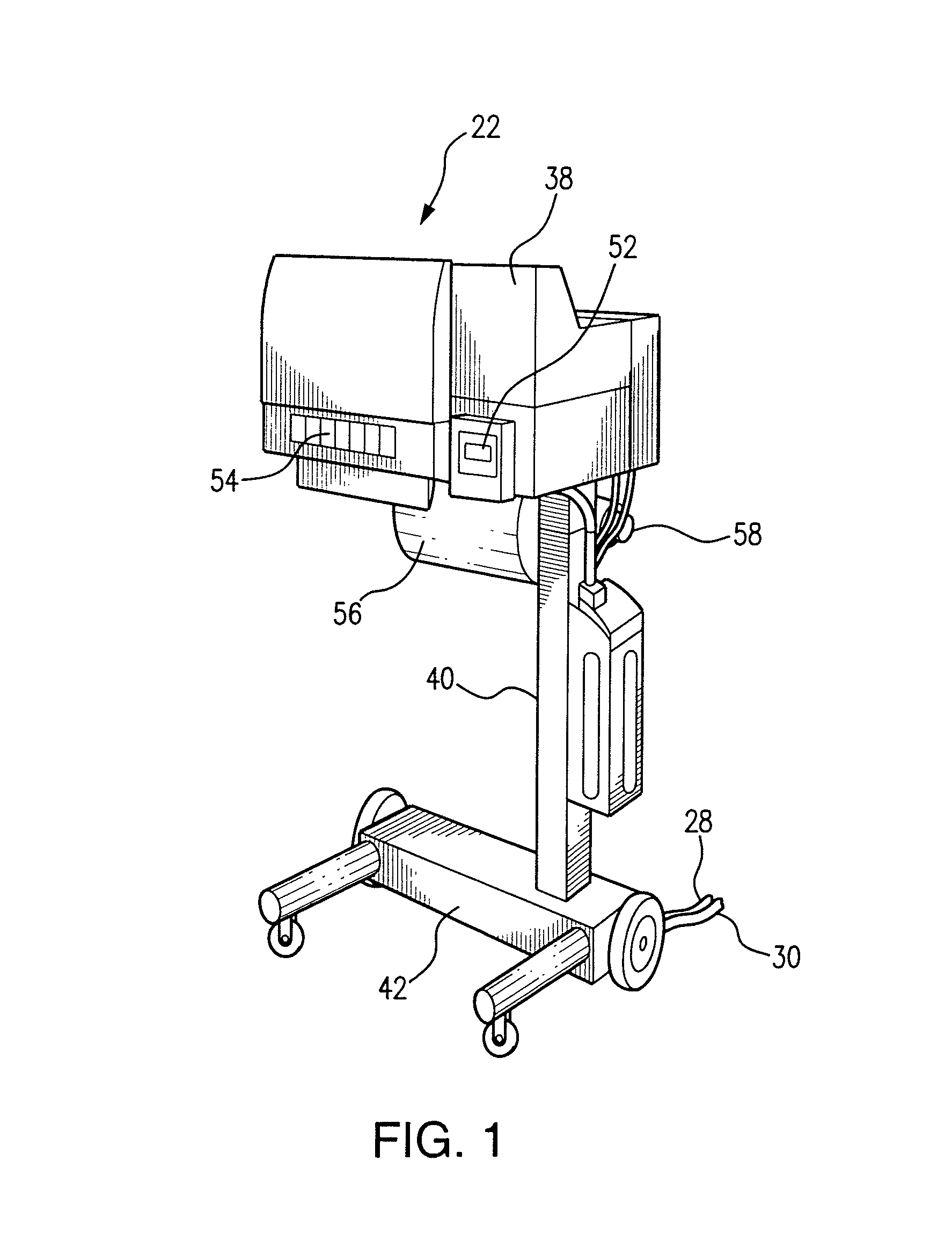
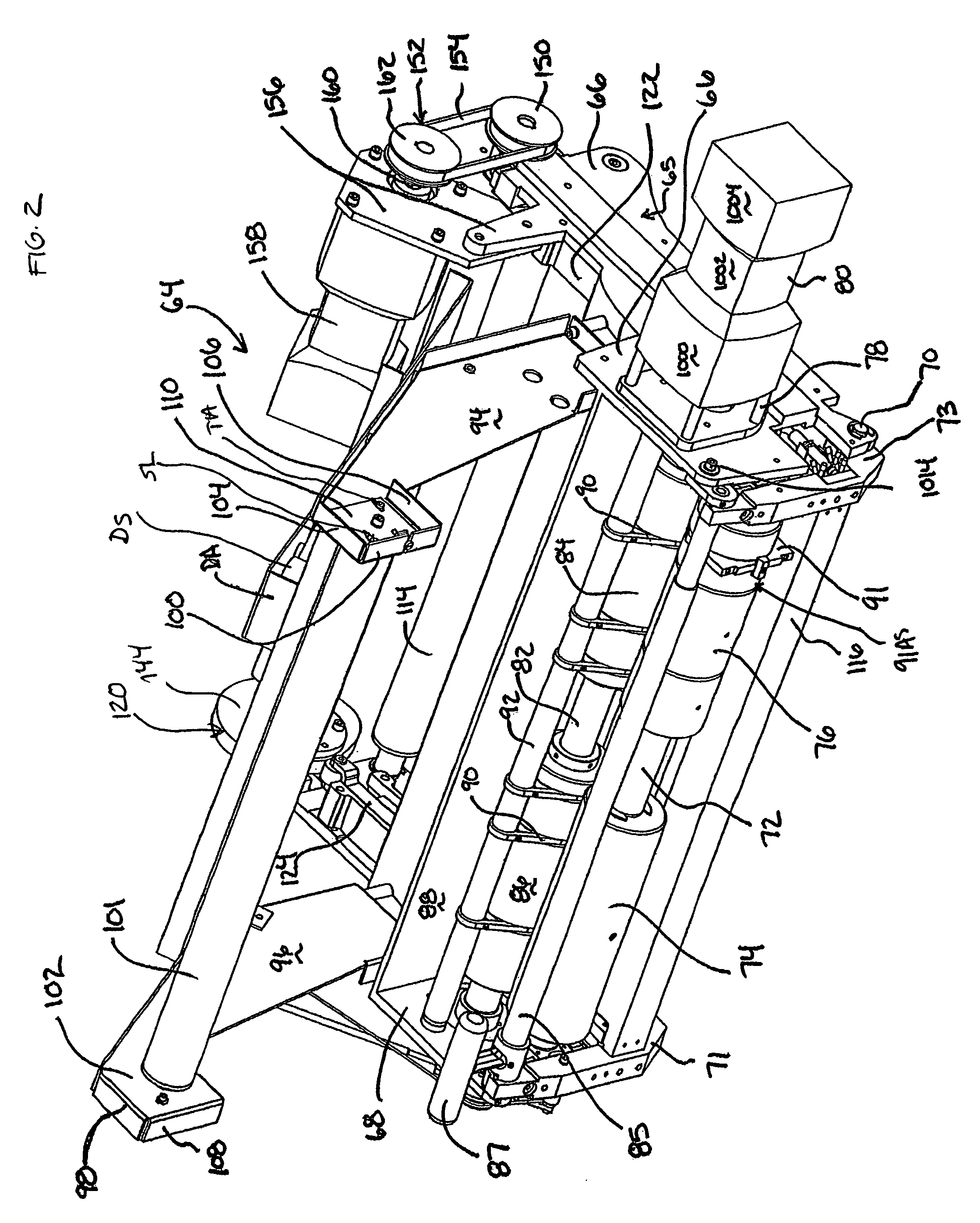
[0156]FIGS. 8 to 67 illustrate in greater detail an embodiment of edge sealer assembly combination 91AS (with two different edge seal types referenced as 91 and 91′ with the letter “A” added to represent components of the second edge sealer assembly embodiment 91′). Edge sealer assembly combination 91AS comprises first and second sub-rollers 1100 and 1102 and edge sealer assembly 91 having edge sealer (or arbor assembly) 1106 on the film contact side of the driven roller and support base (or arbor base) 1108 on the opposite side. FIG. 14 shows each sub-roller 1100 and 1102 having a pocket cavity 1110 and 1112. FIGS. 18 and 20 illustrate sub-roller 1102 with pocket cavity and with the cavity interior surface 1114 having a pair of screw holes 1116 spaced circumferentially (diametrically) around it, that open out at the other end as shown in FIG. 18. Thus, edge seal roller 1102, which is positioned on the side of the edge seal assembly 91 that is closest to the center of elongation of ...

third embodiment

[0199]FIG. 68 illustrates third embodiment edge sealer assembly 91″ of the present invention which, in a preferred embodiment, is configured as an arbor assembly like the two above described first and second edge sealer embodiments utilized with roller mounts in edge seal assembly combinations 91AS′ or some alternate mounting means to place the sealing device at the desired position relative to the film material being sealed. Edge sealer assembly 91″ comprises edge sealer 310 housing body or “arbor body”311 which, in the illustrated preferred embodiment, is formed of an electrically conductive material (e.g. steel) and as a monolithic body with a film-side peripheral edge 3100. A steel arbor body also provides the benefits of low flexibility (e.g., steel, as in a hardened steel, is in the order of 100 times stiffer than “Acetal” plastic). Edge 3100 is preferably formed of an overall convex contour with a less convex or planar intermediate face or presentation section 3101 being prov...


PUM

PropertyMeasurementUnit
surface temperaturesaaaaaaaaaa
diametersaaaaaaaaaa
resistanceaaaaaaaaaa

Abstract

A sealer to bond film having a high temperature resistance (e.g., ceramic) substrate with properly sized groove receiving a heater element as in a flat faced wire band in a tight, flush to adjacent film presentation surface arrangement. A stacked ceramic plate set with wire band within a groove defined by an intermediate stack insert is a suitable substrate. The band is retained flush by a positioner securely locking down one end while the other end is provided at a housing body access location. The sealer is suited for use as a product-in-bag sealing device (products such as air, foam, foodstuff, etc.) with the heater element in contact with film to form a seal. A drag seal arrangement, where film layers are drawn past a fixed or adjustably mounted heater element is an example.

Description

CROSS-REFERENCE TO RELATED APPLICATIONS[0001]The present invention is a continuation-in-part of U.S. Ser. No. 10 / 623,100 filed Jul. 22, 2003, now U.S. Pat. No. 7,213,383 which claims priority of provisional application 60 / 468,988 filed May 9, 2003, with each of these being incorporated herein by reference.FIELD OF INVENTION[0002]The present invention relates to a sealing device, with a preferred embodiment being a sealer with means for localized heating to bond film material as in a resistance heating element applied to film layers such as those used in bag formation.BACKGROUND OF THE INVENTION[0003]Many sealing mechanisms have been created including sealing mechanisms such as those used in “Foam-In-Bag”, “Air-In-Bag” and “Food (or other Product types)-In-Bag” manufacturing devices. Many endeavor to use a sealing wire, heated by electrical resistance, which rolls or drags over the material being sealed. Other sealing techniques have been attempted, including the use of hot melt glue...

Claims


Application Information

Patent Timeline
Patent Type & Authority Patents(United States)
IPC IPC(8): H05B3/06H05B3/20B65B51/30
CPCB29C65/7894B29C66/961B29C66/80B29C66/8167B29C66/91213B29C66/91315B29C66/91313B29C66/91212B29C66/81871B29C65/223B29C66/91231B29C65/228B29C65/229B29C66/91651B29C66/91421B29C66/91431B29C66/91655B29C66/81427B29C66/8122B29C66/43B29C66/1122B29C66/81422B29C65/00B29K2909/02B29K2827/18B29C65/224B29C66/439B29C66/71B29K2023/065
Inventor BERTRAM, GEORGEWALKER, DOUGLAS
Owner PREGIS INTELLIPACK CORP
Why Eureka
Try Eureka