Touch sensor with sliding structure

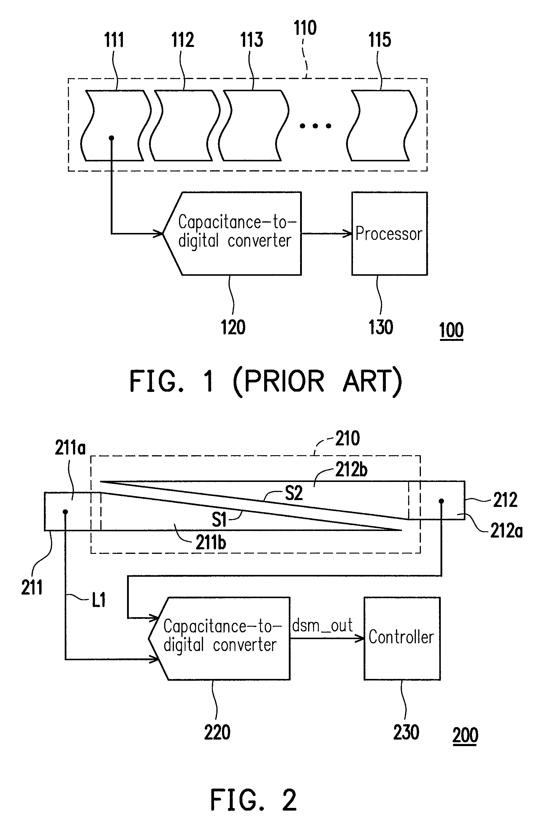
a sliding structure and touch sensor technology, applied in transmission systems, instruments, code conversion, etc., can solve the problems of increasing the cost of the entire touch sensor b>100/b>, and the cost of an electronic device adopting this touch sensor is also increased

Active Publication Date: 2012-02-28
ITE TECH INC
View PDF6 Cites 2 Cited by
  • Summary
  • Abstract
  • Description
  • Claims
  • Application Information

AI Technical Summary

Benefits of technology

[0009]Accordingly, the present invention is directed to a sliding structure touch sensor which can determine the relative position of a touched point on a touch panel.

Problems solved by technology

Thus, the cost of the entire touch sensor 100 is greatly increased, and accordingly, the cost of an electronic device adopting this touch sensor is also increased.

Method used


Image

  • Touch sensor with sliding structure
  • Touch sensor with sliding structure
  • Touch sensor with sliding structure

Examples


Embodiment Construction

[0031]Reference will now be made in detail to the present preferred embodiments of the invention, examples of which are illustrated in the accompanying drawings. Wherever possible, the same reference numbers are used in the drawings and the description to refer to the same or like parts.

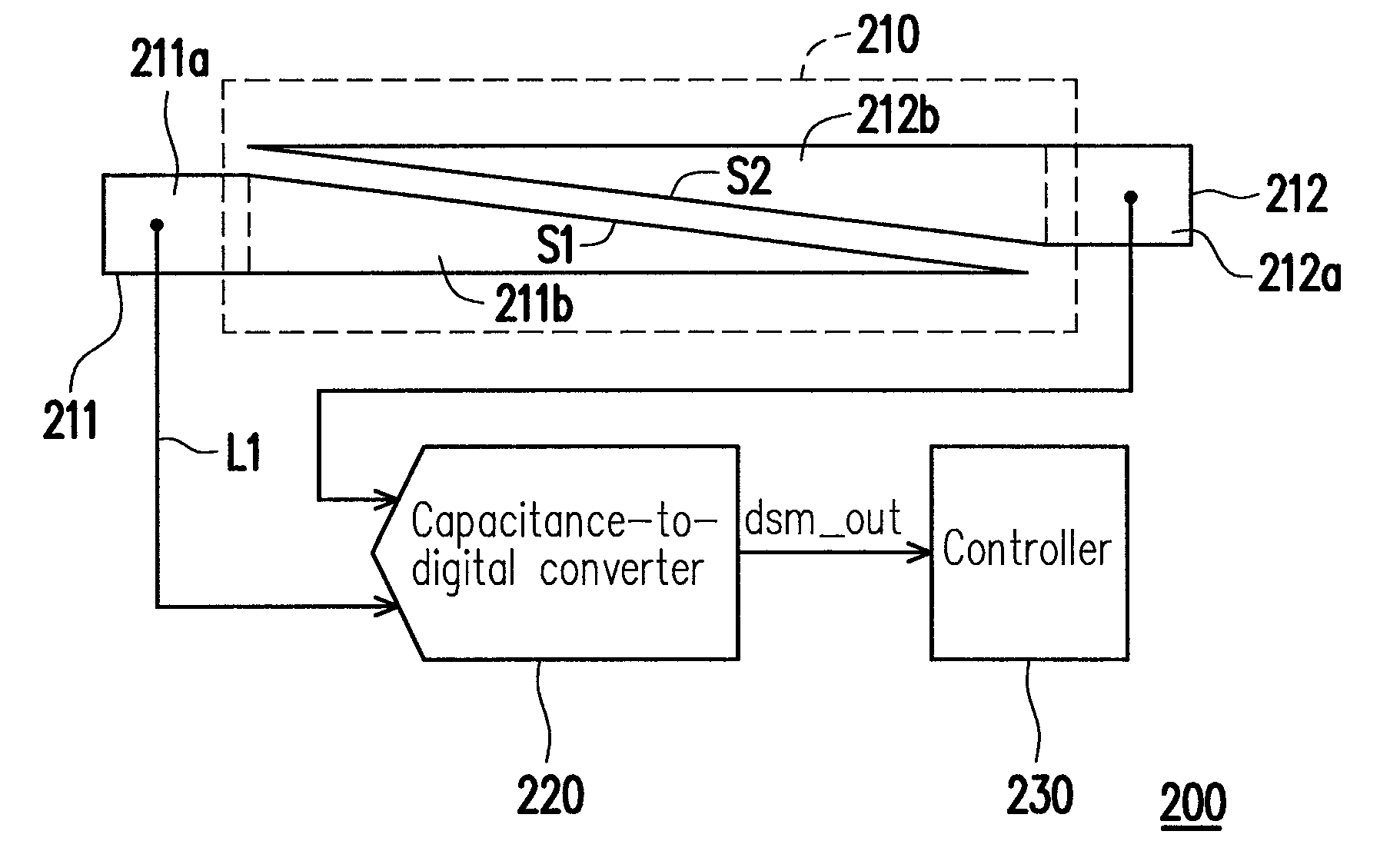
[0032]FIG. 2 is a diagram of a sliding structure touch sensor 200 according to an embodiment of the present invention. Referring to FIG. 2, the touch sensor 200 includes a first touch detecting plate 211, a second touch detecting plate 212, a capacitance-to-digital converter 220, and a controller 230. The first touch detecting plate 211 includes a flat panel portion 211a and a tilt portion 211b. Similarly, the second touch detecting plate 212 includes a flat panel portion 212a and a tilt portion 212b.

[0033]In addition, a bevel edge s2 of the second tilt portion 212b of the second touch detecting plate 212 is parallel to a bevel edge s1 of the first tilt portion 211b of the first touch detecting plat...


PUM


Abstract

A touch sensor with a sliding structure is disclosed. The touch sensor includes a first touch detecting plate, a second touch detecting plate, and a capacitance-to-digital converter. The first touch detecting plate includes a first tilt portion, and the second touch detecting plate includes a second tilt portion, wherein a bevel edge of the second tilt portion is parallel to a bevel edge of the first tilt portion. The first touch detecting plate and the second touch detecting plate form a parallelogram slide detecting area. The first touch detecting plate transmits a first detected capacitance, and the second touch detecting plate transmits a second detected capacitance. The capacitance-to-digital converter generates a sliding state detected value according to the first detected capacitance and the second detected capacitance.

Description

CROSS-REFERENCE TO RELATED APPLICATION[0001]This application claims the priority benefit of Taiwan application serial no. 98116862, filed on May 21, 2009. The entirety of the above-mentioned patent application is hereby incorporated by reference herein and made a part of specification.BACKGROUND OF THE INVENTION[0002]1. Field of the Invention[0003]The present invention generally relates to a touch sensor of a touch panel, and more particularly, to a sliding structure touch sensor of a capacitive touch panel.[0004]2. Description of Related Art[0005]The consumers' demand to the quality and functionality of electronic products has been increasing along with the development of electronic technologies. Meanwhile, many personalized man-machine interfaces have been provided to attract more consumers.[0006]The most common man-machine interface is touch panel. A touch panel is a device which directly receives input signals from a touch head (a finger or a stylus). When a user touches the tou...

Claims


Application Information

Patent Timeline
Patent Type & Authority Patents(United States)
IPC IPC(8): G06F3/045
CPCG01D5/24G01D5/2405H03M1/287
Inventor WU, TZU-YIGUO, LEE-CHUN
Owner ITE TECH INC
Why Eureka
Try Eureka