System for topology based automatic focus

a topology and automatic focus technology, applied in the field of photography, can solve the problems of large time consumption of full search methods, poor user experience, and change in object clarity (focus) to achieve the effect of improving focus speed and accuracy

Active Publication Date: 2012-02-28
AMBARELLA INT LP
View PDF13 Cites 4 Cited by
  • Summary
  • Abstract
  • Description
  • Claims
  • Application Information

AI Technical Summary

Benefits of technology

[0008]The objects, features and advantages of the present invention include providing a system for topology based automatic focus that may (i) improve focus speed and accuracy for objects with low contrast, (ii) allow early termination of a full search, (iii) make focus decisions based on a relationship between focus value and focus point, (iv) make focus decisions based on topology of a focus value curve and / or (v) be used in video cameras.

Problems solved by technology

However, the full search auto-focus method has several drawbacks.
Firstly, to search the entire focus point range, the full search method consumes a large amount of time before finally settling at the correctly-focused point.
The change in object clarity (focus) produces a poor user experience because the user expects the object to not move out of focus (i.e., become blurred) once the object is in focus (i.e., clear).

Method used


Image

  • System for topology based automatic focus
  • System for topology based automatic focus
  • System for topology based automatic focus

Examples


Embodiment Construction

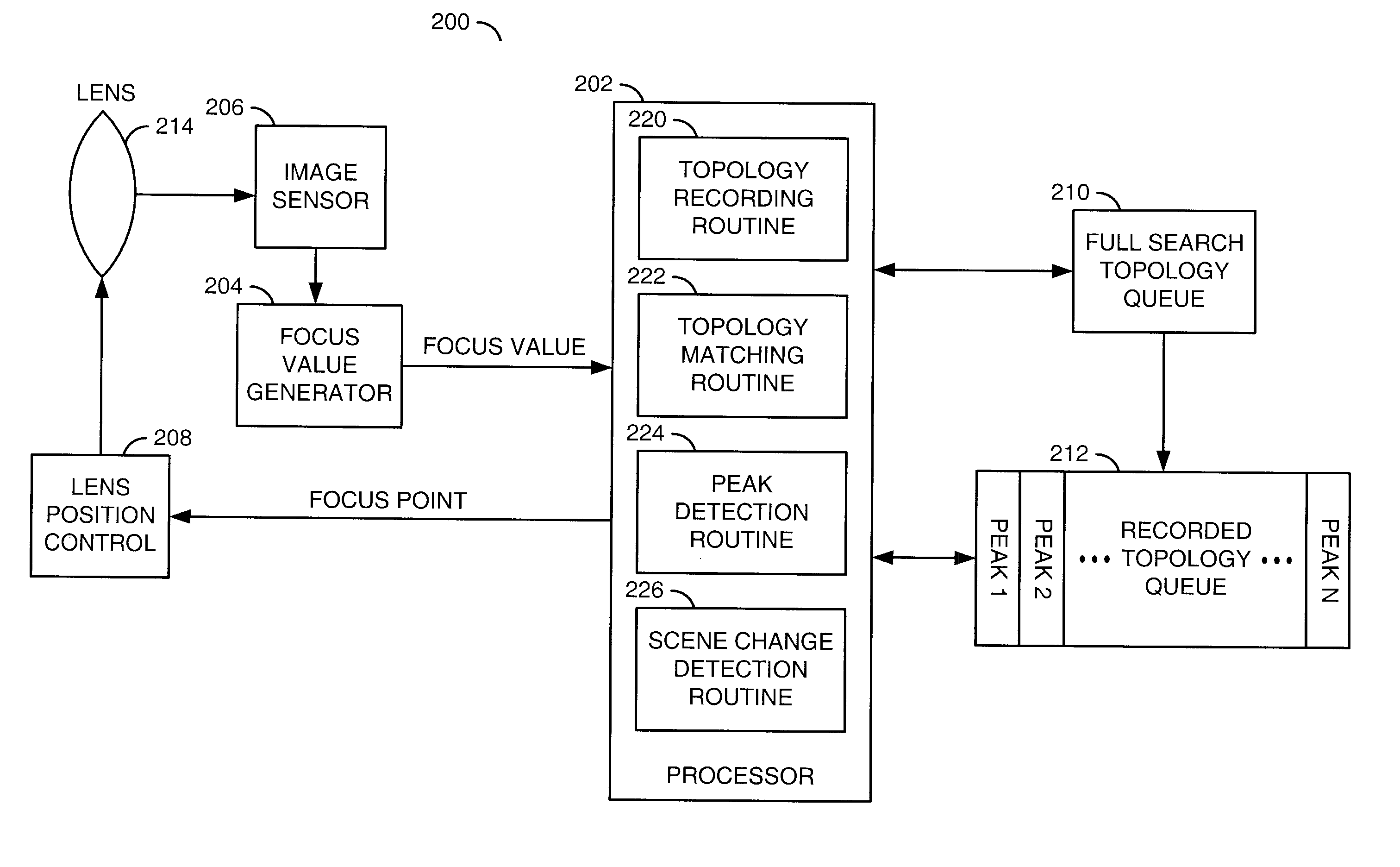
[0020]The present invention may provide a method to improve focus speed and accuracy for an object with low contrast (e.g., an object having a small peak or peaks in the focus value curve). The present invention generally uses a topology of a peak to make focus decisions. The phrase “topology of a peak” (or “topology” for short), as used herein, generally refers to a shape of the focus value curve surrounding a peak.

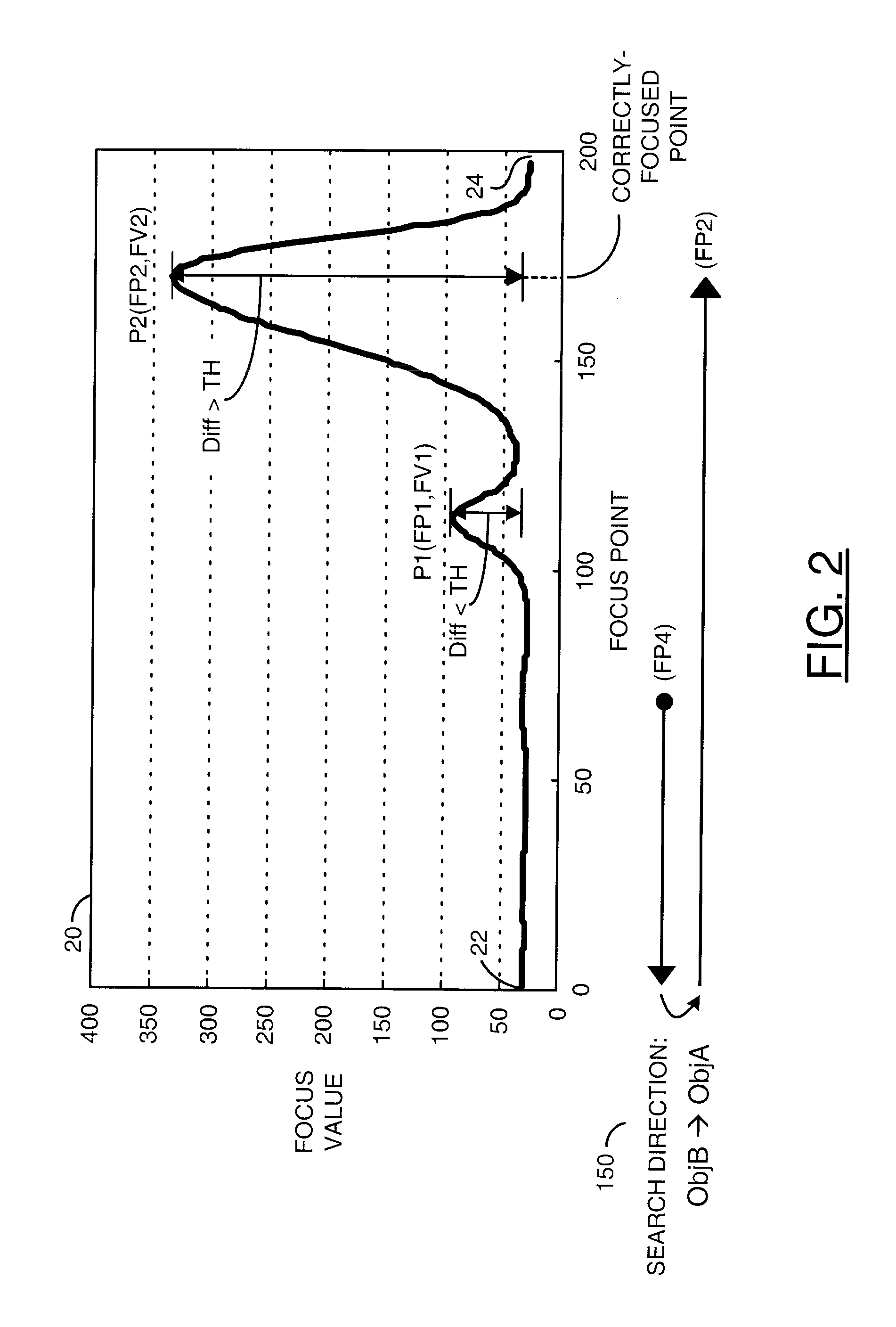
[0021]Referring to FIG. 2, a diagram is shown illustrating an example focus value curve 20 of an object A (ObjA). In one example, the focus value curve 20 of the object A may have two peaks (e.g., P1 and P2). Local maximum focus values (FV) and related focus points (FP) of the peaks P1 and P2 may be denoted as (FP1, FV1) and (FP2, FV2), respectively. Because the peak P2 has the largest local maximum focus value the focus value FV2 may be referred to as the global maximum focus value. The correctly-focused point for the object A is at FP2. A possible solution to the disad...


PUM


Abstract

A method for automatically focusing a camera including the steps of (A) recording a first topology and a second topology, where the second topology occurs temporally after the first topology, and (B) comparing the first topology with the second topology. A focus of the camera is automatically adjusted based upon one or more similarities between the first topology and the second topology.

Description

FIELD OF THE INVENTION[0001]The present invention relates to photography generally and, more particularly, to a system for topology based automatic focus.BACKGROUND OF THE INVENTION[0002]In a video camera, a position of an object lens is varied to image an object, at various distances, onto a sensor. The position of the object lens is referred to as the “focus point.” The image on the sensor can be processed to measure contrast. The contrast measurement is referred to as a “focus value.” The focus value can be generated by deriving a high pass signal of the image formed on the sensor. The maximum focus value occurs when the object lens is at a position where a clear and sharp image is produced on the sensor. The position where a clear and sharp image is produced on the sensor is called the “correctly-focused point.”[0003]Referring to FIG. 1, a diagram of an example focus value curve 10 is shown. The focus value curve 10 illustrates a relationship between focus value and focus point ...

Claims


Application Information

Patent Timeline
Patent Type & Authority Patents(United States)
IPC IPC(8): H04N5/232
CPCH04N5/23212H04N23/673
Inventor HUANG, HSIANG-CHUNJU, CHIHONG JOHN
Owner AMBARELLA INT LP
Why Eureka
Try Eureka