
Device for air-cooling electronic apparatus

a technology for electronic devices and air-cooling, which is applied in the direction of electrical apparatus casings/cabinets/drawers, cooling/ventilation/heating modifications, instruments, etc. it can solve the problems of shortening the life of electronic parts, disadvantageous space saving and manufacturing costs of devices, and inconvenient installation and removal of devices, so as to improve the capacity of cooling a heat-producing part and prevent accumulation of dust on the heat-producing part. , the

Active Publication Date: 2012-02-28
JVC KENWOOD CORP A CORP OF JAPAN
View PDF35 Cites 12 Cited by
  • Summary
  • Abstract
  • Description
  • Claims
  • Application Information

AI Technical Summary

Benefits of technology

The present invention provides a device for air-cooling an electronic apparatus. The device has a suction opening and a discharge opening, and a fan generates airflow inside the housing to release heat produced by the electronic part. The device also has multiple air introduction plates with projections that change the direction of airflow, and air lead-through boards at a downstream region of the air introduction plates. The device can easily be attached or detached to the housing, and prevents accumulation of dust on the heat-producing part while increasing the cooling capacity without increasing the size of the device.

Problems solved by technology

If no maintenance is performed, dust causes the parts in the inside of the housing to be short-circuited, thus causing a failure.
However, such an air-cooling device is not suitable for a model having a large amount of heat production because clogging of the filter reduces air-intake to lower the capacity for cooling.
In this structure, however, stationary air surrounding the printed boards 8, 8 are cooled via the chassis 3, so sufficient capacity for cooling is not obtained; the temperature of air surrounding the printed boards 8, 8 rises to raise the temperature of electronic parts mounted on the printed boards 8, 8 thus shortening the life of the electronic parts.
In either case, however, the device is disadvantageous in space saving and manufacturing cost.

Method used


Image

  • Device for air-cooling electronic apparatus
  • Device for air-cooling electronic apparatus
  • Device for air-cooling electronic apparatus

Examples


Embodiment Construction

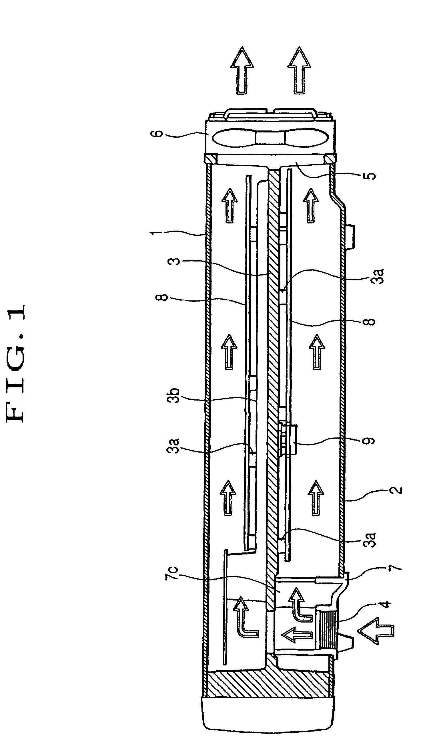
[0035]A preferred embodiment to implement the present invention will be described below with reference to an embodiment. FIG. 1 is a cross-sectional view illustrating a device for air-cooling an electronic apparatus according to an embodiment of the present invention. An upper housing 1 and a lower housing 2 illustrated in FIG. 1 are coupled to sandwich a chassis 3 and constitutes a housing that contains an electronic apparatus. Suction openings 4, 4, . . . which will be illustrated in detail in FIG. 4 are provided in a dustproof unit 7 attached so as to seal a hole of the lower housing 2; and a discharge opening 5 is provided in a chassis 3, or the upper housing 1 and the lower housing 2. Further, a fan 6 is secured to the chassis 3.

[0036]Bosses 3a, 3a, . . . and radiation fin 3b are formed in the chassis 3; and printed boards 8, 8 are fastened to the bosses 3a, 3a, . . . . Heat produced by a maximum-heat-producing part 9 mounted on the printed boards 8 is transmitted via the heat ...


PUM


Abstract

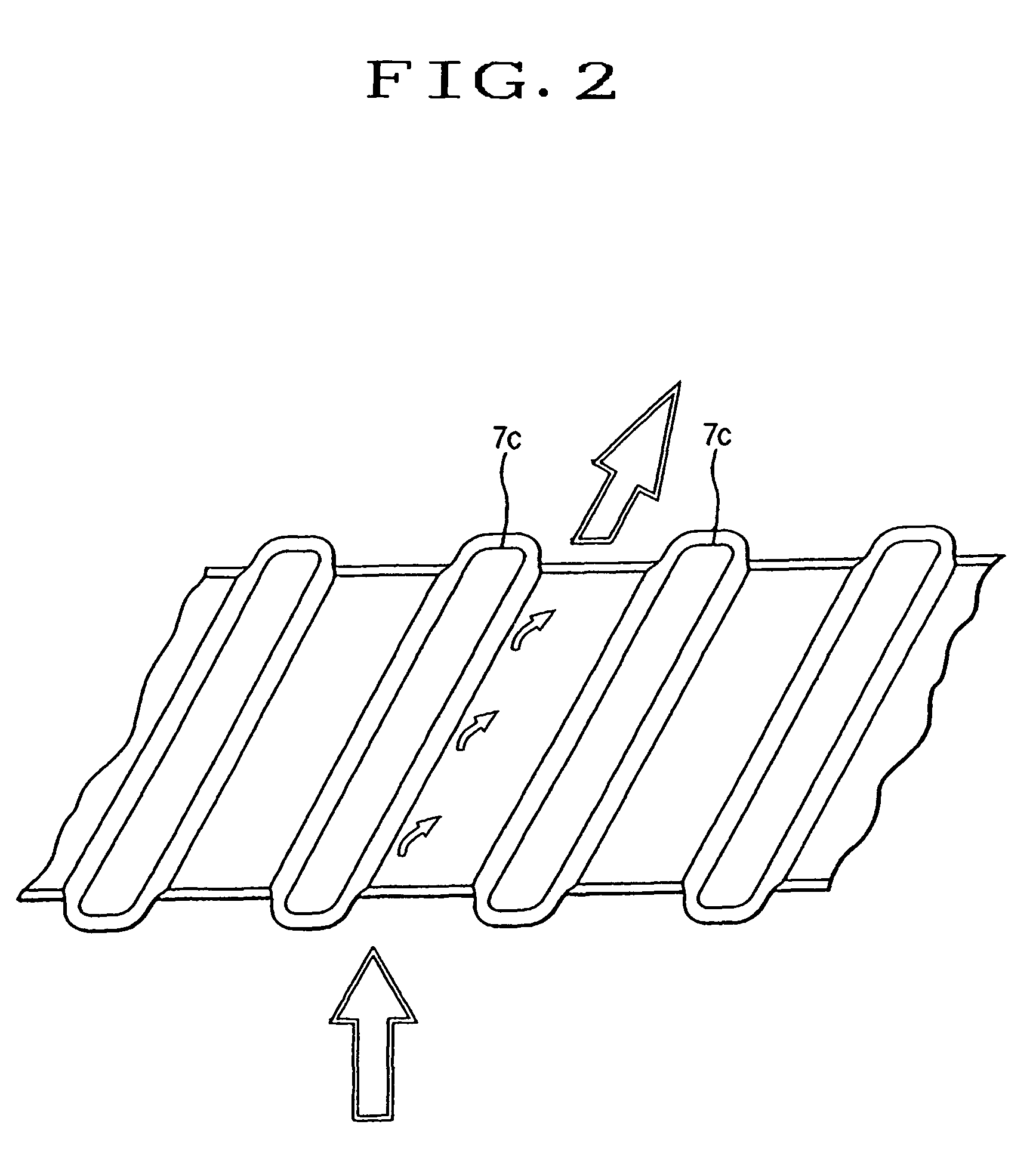
A device for air-cooling an electronic apparatus, where a suction opening (4) is provided in a housing (1), discharge openings (5) are provided in housings (1, 2), an airflow passing the inside of the housings is generated by a fan (6), and heat produced by a heart-producing body (9) is released to the outside of the housings by the airflow. Air introduction plates inclined to change the direction of the airflow are arranged at the suction opening (4), and a large number of projections are formed on the surfaces of the air introduction plates. The device for air-cooling an electronic apparatus has increased capacity for cooling a heat-producing part without increase in the size of the device, and in the device, accumulation of dust on the heat-producing part can be prevented.

Description

TECHNICAL FIELD[0001]The present invention relates to an electronic apparatus, and more particularly to an air-cooling device for the same.BACKGROUND ART[0002]An exemplary conventional device for air-cooling an electronic apparatus will be described with reference to FIG. 5. An upper housing 1 and a lower housing 2 illustrated in FIG. 5 are coupled to sandwich a chassis 3 and constitutes a housing that contains an electronic apparatus. Suction openings 4, 4 are provided in each of the upper housing 1 and the lower housing 2; and a discharge opening 5 is provided in the chassis 3, or the upper housing 1 and the lower housing 2. A fan 6 is secured to the chassis 3.[0003]Further, bosses 3a, 3a, . . . and radiation fins 3b, 3b, . . . are formed in the chassis 3; and printed boards 8, 8, . . . are fastened to the bosses 3a, 3a, . . . . Heat produced by a maximum-heat-producing part 9 mounted on the printed boards 8, 8, . . . is transmitted via the heat transmitting parts to the chassis 3...

Claims


Application Information

Patent Timeline
Patent Type & Authority Patents(United States)
IPC IPC(8): H05K7/20
CPCH05K7/20145H05K7/20154
Inventor MIYOSHI, TOYOKAZU
Owner JVC KENWOOD CORP A CORP OF JAPAN
Learn More