Method and system for optically coupling a laser with a transducer in an energy assisted magnetic recording disk drive

a technology of energy-assisted magnetic recording and optical coupling, which is applied in the field of conventional energy-assisted magnetic recording (eamr) disk drive 10, can solve the problems of increasing the insertion loss of laser light, affecting the efficiency of light delivery, and challenging the manufacture of conventional eamr transducers b>10/b> at an acceptable cost and efficiency

Active Publication Date: 2012-02-28
WESTERN DIGITAL TECH INC
View PDF13 Cites 166 Cited by
  • Summary
  • Abstract
  • Description
  • Claims
  • Application Information

AI Technical Summary

Benefits of technology

[0007]FIG. 1 depicts a side view of a conventional EAMR disk drive.

Problems solved by technology

Although the conventional EAMR transducer 10 may function, manufacturing the conventional EAMR transducer 10 at an acceptable cost and efficiency of light delivery may be challenging.
Accurately placing the conventional slider 20 and conventional laser diode 30 using such a conventional system may result in misalignments.
Such misalignments may increase insertion loss of the laser light.
Thus, efficiency of light delivery may suffer.
Similarly, use of a fiber optic cable to couple light from the laser 30 to the transducer 22 may be mechanically unstable and increase the cost of the conventional EAMR transducer 10.
In addition, manufacturing yield and / or manufacturing time may suffer.

Method used


Image

  • Method and system for optically coupling a laser with a transducer in an energy assisted magnetic recording disk drive
  • Method and system for optically coupling a laser with a transducer in an energy assisted magnetic recording disk drive
  • Method and system for optically coupling a laser with a transducer in an energy assisted magnetic recording disk drive

Examples


Embodiment Construction

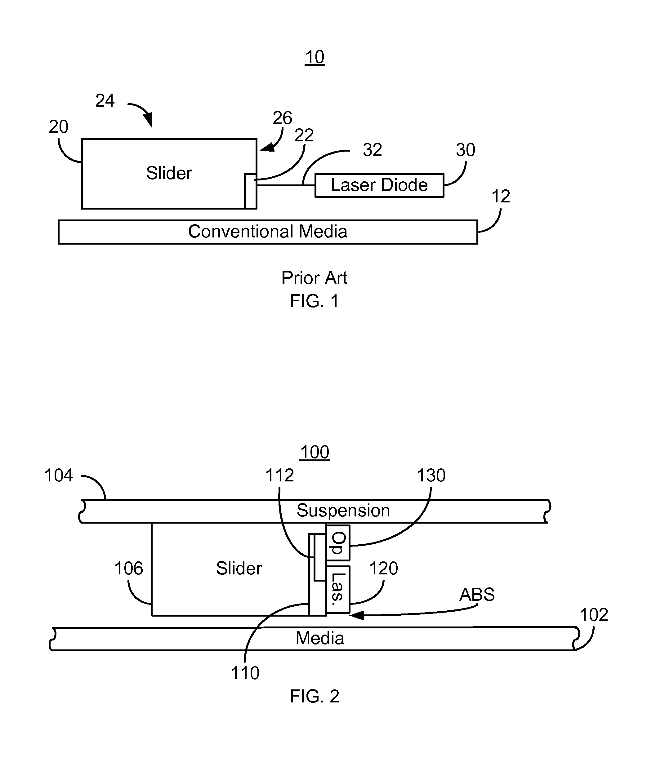
[0016]FIG. 2 is a diagram depicting a portion of an EAMR disk drive 100. For clarity, FIG. 2 is not to scale. For simplicity not all portions of the EAMR disk drive 100 are shown. In addition, although the disk drive 100 is depicted in the context of particular components other and / or different components may be used. Further, the arrangement of components may vary in different embodiments. The EAMR disk drive 100 includes media 102, suspension 104, a slider 106, an EAMR transducer 110 having one or more gratings 112, laser(s) 120, and optics 130. In some embodiments, the laser 120 is a laser diode. The EAMR transducer 110 is coupled with the laser 120. In one embodiment, the EAMR transducer 110 is optically coupled to the laser 120 through the grating 112. Although described as coupled to the slider 106, the EAMR transducer 110 may be considered to be fabricated as part of the slider 106.

[0017]The laser 120 and optics 130 are coupled with the trailing face of the slider 106. Energy...


PUM

PropertyMeasurementUnit
diameteraaaaaaaaaa
diameteraaaaaaaaaa
angleaaaaaaaaaa

Abstract

A method and system for providing an energy assisted magnetic recording (EAMR) disk drive are described. A media for storing data and a slider are provided. The slider has a back side, a trailing face, and an air-bearing surface (ABS) opposite to the back side. At least one laser is coupled with the trailing face of the slider, and has an optic axis substantially parallel to the trailing face. The laser(s) provide energy substantially along the optic axis. Optics are coupled with the trailing face of the slider and receive the energy from the laser(s) via free space. At least one EAMR transducer coupled with the slider. At least part of the EAMR transducer resides in proximity to the ABS. The optics direct the energy from the laser(s) to the EAMR transducer(s). The EAMR transducer(s) receive the energy from the optics and write to the media using the energy.

Description

BACKGROUND[0001]FIG. 1 depicts a side view of portion of a conventional energy assisted magnetic recording (EAMR) disk drive 10. The conventional EAMR disk drive 10 includes a recording media 12, a conventional slider 20, and a conventional laser diode 30 that are typically attached to a suspension (not shown). Other components that may be part of the conventional EAMR disk drive 10 are not shown. The conventional slider 20 includes a back side 24 and a trailing face 26. The conventional slider 20 is typically attached to the suspension at its back side 24. A conventional EAMR transducer 22 is coupled with the slider 20 on the trailing face 26 of the slider.[0002]The conventional EAMR transducer 22 includes a grating (not separately shown) on the trailing face 26. Light from the conventional laser diode 30 is provided substantially along the optic axis 32 of the conventional laser diode 30 to the grating of conventional EAMR transducer 22. In some conventional EAMR disk drives, an o...

Claims


Application Information

Patent Timeline
Patent Type & Authority Patents(United States)
IPC IPC(8): G11B11/00
CPCG11B5/105G11B5/6088G11B2005/0021
Inventor LI, RUOLINTRAN, UTHU, YUFENGLI, JINSHAN
Owner WESTERN DIGITAL TECH INC
Why Eureka
Try Eureka