Laser light source apparatus, and monitoring apparatus and image display apparatus using the same

a technology of laser light source and monitoring apparatus, applied in the direction of instruments, semiconductor lasers, optics, etc., can solve the problems of reducing the image quality of the projected image, speck noise appearing on the image projection screen, and problems not only in the light source apparatus used, so as to reduce the coherence of laser light emitted

Active Publication Date: 2012-02-28
SEIKO EPSON CORP
View PDF16 Cites 107 Cited by
  • Summary
  • Abstract
  • Description
  • Claims
  • Application Information

AI Technical Summary

Benefits of technology

[0007]An advantage of some aspects of the invention is to reduce the coherence of the laser light emitted from a laser light source having a wavelength conversion element.
[0009]According to this configuration, the second laser array light source emits laser light having a wavelength different from that of the laser light emitted from the first laser array light source. The laser light that exist from the laser light source apparatus therefore contains a plurality of laser light having wavelengths different from one another, so that the coherence of the laser light that exits from the laser light source apparatus can be reduced.
[0011]According to this configuration, the wavelength selection elements provided in the cavities are used to set the laser oscillation wavelengths of the first and second fundamental wave laser arrays, so that the laser light emitted from the first and second laser array light sources can be of different wavelengths. Further, the use of the wavelength selection elements of the same type can prevent increase in the number of types of the wavelength selection element to be used.
[0013]According to this configuration, oscillation can occur in the fundamental wave laser array either at the first or second original wavelength by setting the gain band of the fundamental wave laser array. It is therefore not necessary to set different transmission wavelengths for the wavelength selection elements in the first and second fundamental wave laser arrays.
[0019]According to this configuration, the wavelength conversion is carried out by the wavelength conversion element appropriate to the first original wavelength and the wavelength conversion element appropriate to the second original wavelength. The wavelength conversion efficiencies can therefore be higher both in the first and second laser array light sources.
[0021]According to this configuration, the use of the wavelength conversion elements of the same type can prevent increase in the number of types of the wavelength conversion element to be used.

Problems solved by technology

Laser light interference therefore occurs, so that speckle noise appears on the image projection screen of the image display apparatus.
Such speckle noise could disadvantageously reduce image quality of the projected image.
Such a problem may occur not only in the light source apparatus used in an image display apparatus but also in various apparatuses that require light source apparatuses, such as illumination apparatuses

Method used


Image

  • Laser light source apparatus, and monitoring apparatus and image display apparatus using the same
  • Laser light source apparatus, and monitoring apparatus and image display apparatus using the same
  • Laser light source apparatus, and monitoring apparatus and image display apparatus using the same

Examples


first embodiment

A. First Embodiment

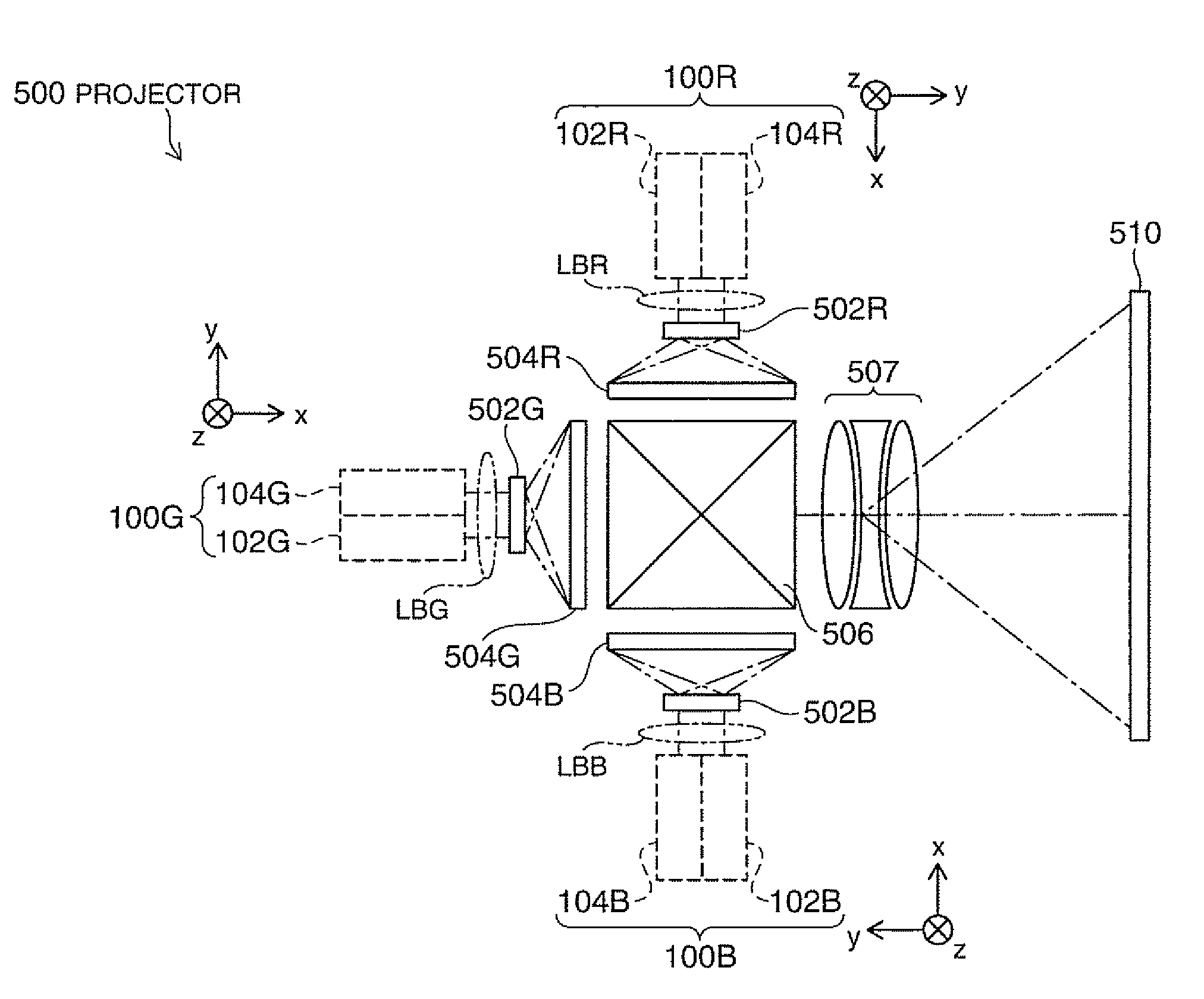
[0052]FIG. 1 is a schematic configuration diagram of a projector to which a first embodiment of the invention is applied. The projector 500 includes a red light emitting laser light source apparatus 100R, a green light emitting laser light source apparatus 100G and a blue light emitting laser light source apparatus 100B. The red laser light source apparatus 100R is formed by stacking two laser array light sources 102R and 104R, each emitting red laser light. Similarly, the green laser light source apparatus 100G is formed by stacking green laser array light sources 102G and 104G, and the blue laser light source apparatus 100B is formed by stacking blue laser array light sources 102B and 104B.

[0053]The projector 500 further includes homogenizing optical systems 502R, 502G, and 502B and liquid crystal light valves 504R, 504G, and 504B for respective colors. The projector 500 further includes a cross dichroic prism 506 and a projection lens 507. The cross dichroic pr...

second embodiment

B. Second Embodiment

[0070]FIG. 4A is a configuration diagram showing the configuration of the laser light source apparatus 100a in a second embodiment. The laser light source apparatus 100a of the second embodiment differs from the laser light source apparatus 100 of the first embodiment shown in FIG. 3A in that the configuration of a first laser array light source 102a is different. Specifically, a VCSEL array 110a and a wavelength conversion element 130a differ from the VCSEL array 110 and the wavelength conversion element 130 in the first embodiment. The other components are the same as those in the first embodiment. FIG. 4B shows the positional relationship of the exit positions of the beams W14a, W24 that exit from the laser light source apparatus 100a of the second embodiment with respect to the packages 170 for the laser array light sources 102a and 104. The positional relationship is the same as that in the first embodiment shown in FIG. 3B except that the exit beam W14 is r...

third embodiment

C. Third Embodiment

[0080]FIG. 6A is a configuration diagram showing the configuration of the laser light source apparatus 100b in a third embodiment. The laser light source apparatus 100b of the third embodiment differs from the laser light source apparatus 100a of the second embodiment shown in FIG. 4A in that the wavelength conversion element in the first laser array light source 102a is replaced with the wavelength conversion element 130 of the same wavelength as the wavelength conversion element 130 in the second laser array light source 104, and in that the temperature Ts of the wavelength conversion element 130 in the first laser array light source 102a is set to 20° C. The other components are the same as those in the second embodiment.

[0081]As described above, the optical length of the domain pitch of the wavelength conversion element 130 varies with the temperature of the wavelength conversion element 130. When PPLN is used, as in the case of the third embodiment, the optim...


PUM


Abstract

A laser light source apparatus includes a first laser array light source that emits first-wavelength light, and a second laser array light source that emits second-wavelength light, the second wavelength being different from the first wavelength. The first laser array light source includes a first fundamental wave laser array that produces first fundamental wave light having a first original wavelength, and a first wavelength conversion element that wavelength-converts the first fundamental wave light into the first-wavelength light. The second laser array light source includes a second fundamental wave laser array that produces second fundamental wave light having a second original wavelength different from the first original wavelength, and a second wavelength conversion element that wavelength-converts the second fundamental wave light into the second-wavelength light.

Description

BACKGROUND[0001]1. Technical Field[0002]The present invention relates to a laser light source apparatus having a wavelength conversion element.[0003]2. Related Art[0004]To enhance the brightness of an image display apparatus, such as a projector, a laser light source is used as the light source apparatus in some cases. Such a laser light source uses a more efficient, longer-wavelength laser light source and a wavelength conversion element to provide visible laser light.[0005]JP-T-2004-503923 is an example of related art (the term “JP-T” as used herein means a published Japanese translation of a PCT patent application).[0006]The visible laser light provided by such wavelength conversion, however, also has higher coherence than that of a discharge lamp light source and the like. Laser light interference therefore occurs, so that speckle noise appears on the image projection screen of the image display apparatus. Such speckle noise could disadvantageously reduce image quality of the pr...

Claims


Application Information

Patent Timeline
Patent Type & Authority Patents(United States)
IPC IPC(8): H01S5/00
CPCG03B21/26H04N9/3129H04N9/3161H01S3/109H01S5/02248H01S5/14H01S5/141H01S5/4012H01S5/4087H01S5/423H01S5/02325
Inventor TAKEDA, TAKASHI
Owner SEIKO EPSON CORP
Why Eureka
Try Eureka