Methods of manufacturing highly integrated SMA actuators

a technology of actuators and actuator parts, applied in the direction of closed-circuit machines/engines, hot gas positive displacement engine plants, etc., can solve the problems of low ultimate tensile strength of materials, insufficient protection mechanisms of existing sma actuators, and inability to commercially viable use of smas, so as to prevent sma component damage

Active Publication Date: 2012-03-06
ALFMEIER PRAZISION BAUGRUPPEN & SYSTLOSUNGEN
View PDF76 Cites 19 Cited by
  • Summary
  • Abstract
  • Description
  • Claims
  • Application Information

AI Technical Summary

Benefits of technology

[0005]An SMA actuator assembly is provided. The SMA actuator assembly includes a SMA component coupled to an output shaft such that SMA actuation results in output shaft movement. Additionally, a return force component is coupled to the SMA component to move the SMA component from a contracted configuration to an extended configuration. In some instances, the return force component imparts a non-linear return force to the SMA component. Additionally, the SMA actuator assembly includes a protective mechanism to prevent SMA component damage.

Problems solved by technology

Commercially viable uses for SMAs remained elusive until the 1990s.
For example, many existing SMA actuators have insufficient protective mechanisms to ensure safe, reliable and extended lifetime operation of the SMA materials employed in the actuator.
However, while SMA wires typically have high material strength they have low ultimate tensile strength.
SMA wire failure may result in catastrophic failure of the overall actuator.

Method used


Image

  • Methods of manufacturing highly integrated SMA actuators
  • Methods of manufacturing highly integrated SMA actuators
  • Methods of manufacturing highly integrated SMA actuators

Examples


Embodiment Construction

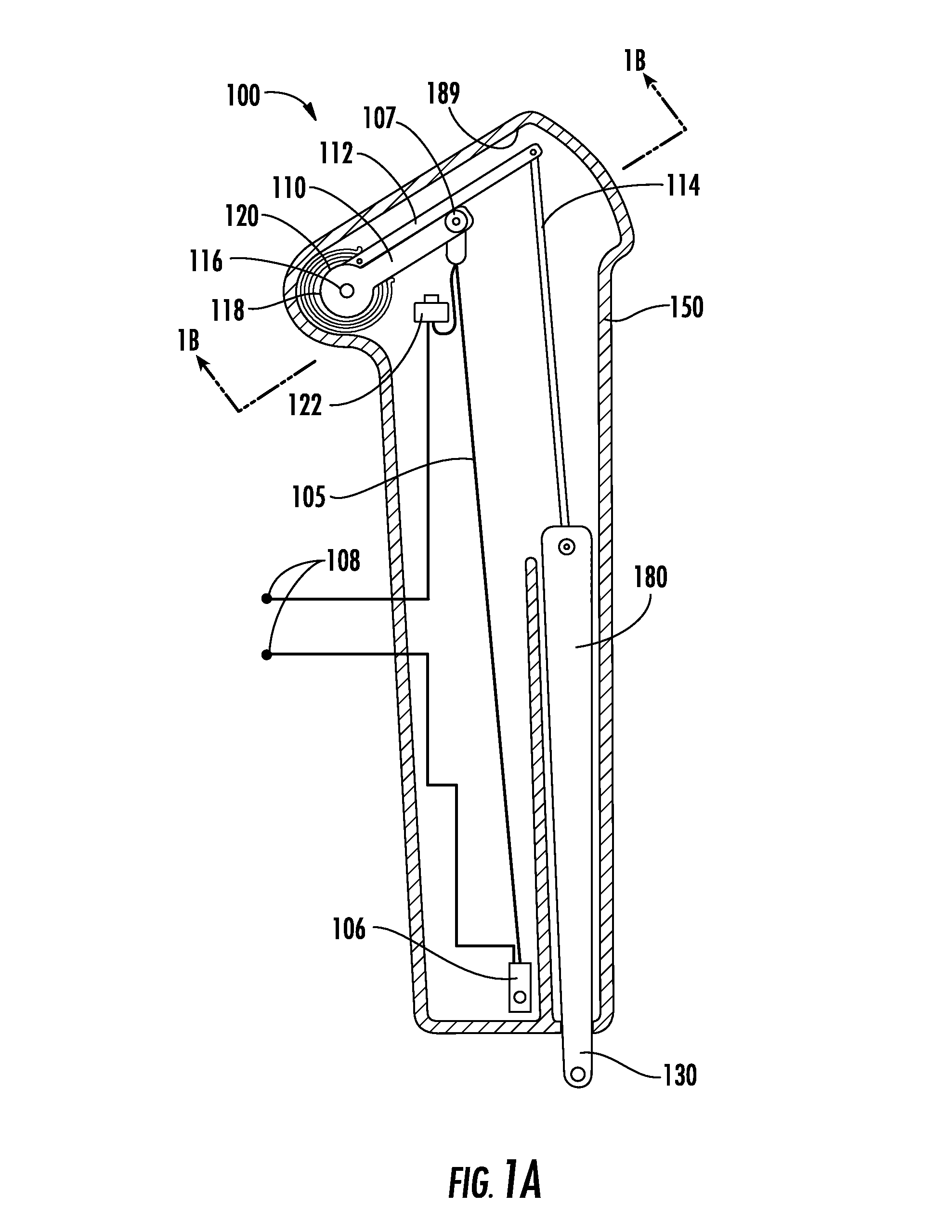
[0033]FIG. 1A is a top-down view of an embodiment of an SMA actuator assembly 100 according to the present invention. The SMA actuator assembly 100 includes an SMA component 105, a drive member 110, an output member 112, a linkage 114, and an output shaft 180 disposed inside of a protective casing 150. In this embodiment of the SMA actuator assembly 100, the SMA component 105 is an SMA wire. The SMA wire 105 is suitably attached within the casing 150 at attachment point 106 and to drive member 110 at attachment point 107. Terminal connectors 108 provide activation energy (i.e., electrical current) to the SMA wire 105. A protective mechanism, here a limit switch 122, is connected in-line with the power supplied to the SMA wire 105. The operation of the limit switch 122 is described below.

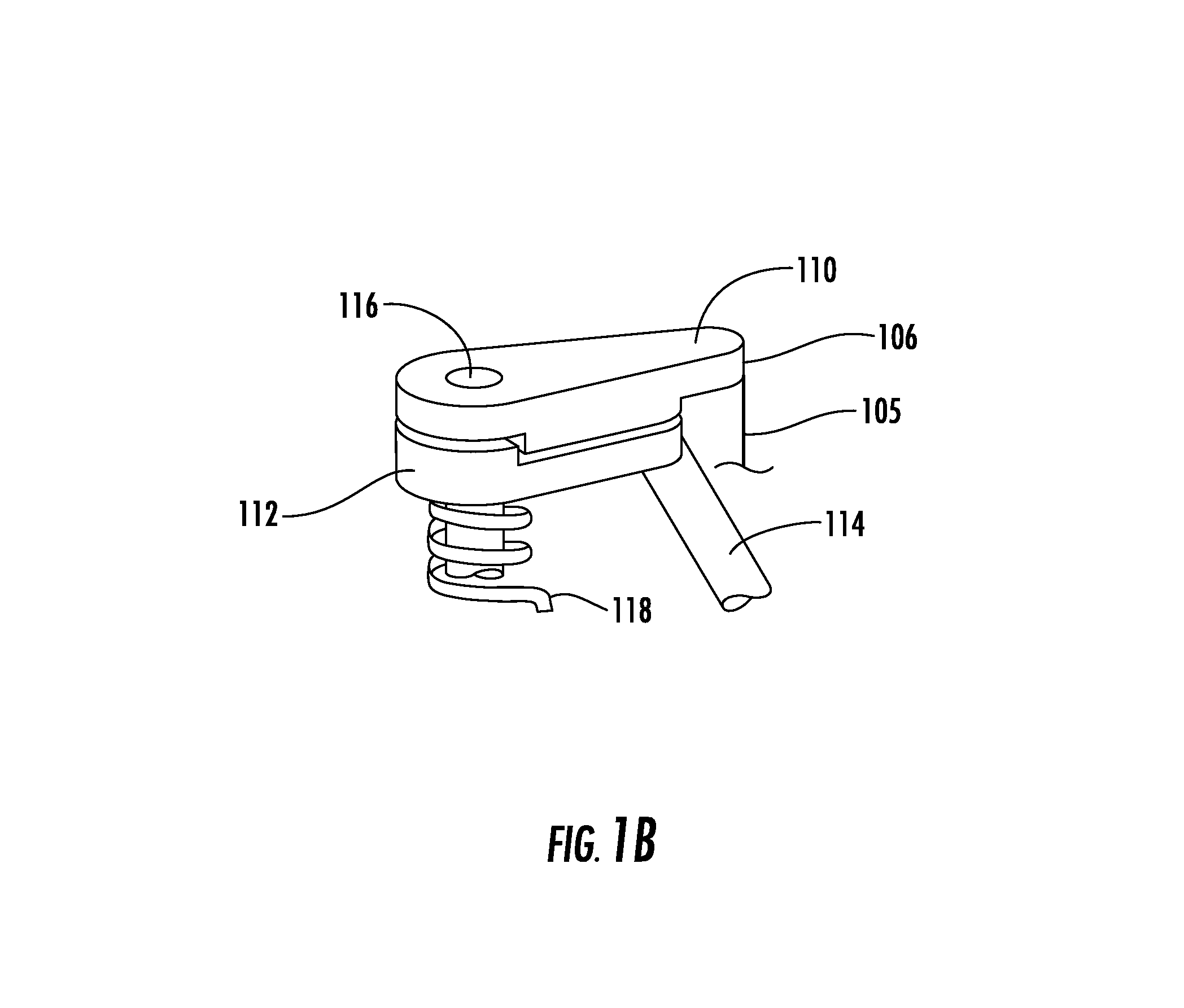
[0034]The particular arrangement of the drive member 110 and the output member 112 will now be described through reference to FIG. 1A in conjunction with FIG. 1B. The drive member 110 is attached to ...


PUM


Abstract

A shape memory alloy (SMA) actuator assembly is provided that includes an SMA component. The SMA component is used to impart motion in an output shaft. Also provided is a return force component that provides a variable, tailored return force to the SMA component. Additionally, a variety of protective mechanisms are disclosed and utilized to prevent damage to the internal workings and components within the SMA actuator assembly as well as provide protection and safety for external workings.

Description

CROSS REFERENCE TO RELATED APPLICATIONS[0001]This application claims priority under 35 U.S.C. §120 to U.S. patent application Ser. No. 10 / 431,173, filed May 6, 2003, which claims benefit under 35 U.S.C. 119(e) of U.S. Provisional Patent Ser. No. 60 / 378,445, filed May 6, 2002, and also claims benefit under 35 U.S.C. §119(e) of U.S. Provisional Patent Application Ser. No. 60 / 561,072, filed Apr. 8, 2004. The above applications are all incorporated herein by reference in their entirety.FIELD OF INVENTION[0002]The present invention relates to actuator assemblies, and more particularly to actuator assemblies that employ shape memory alloy materials and integrated protective mechanisms, as well as manufacturing techniques and resulting structures.BACKGROUND OF INVENTION[0003]The thermoelastic properties of shape memory alloys (SMA) have been known since the 1930s. Experimental use of SMAs continued for decades. Commercially viable uses for SMAs remained elusive until the 1990s. Today, SMA ...

Claims


Application Information

Patent Timeline
Patent Type & Authority Patents(United States)
IPC IPC(8): F01B29/10
CPCF03G7/065
Inventor VON BEHRENS, PETER E.FAIRBANKS, DYLAN M.
Owner ALFMEIER PRAZISION BAUGRUPPEN & SYSTLOSUNGEN
Why Eureka
Try Eureka