Method and device for controlling at least one rotating component of a printing press

a technology of rotating components and printing presses, applied in the direction of rotary presses, printing, office printing, etc., can solve the problems of insufficient constantness and the rotational speed may be changed only extremely slowly, and achieve the effect of constant ink density

Inactive Publication Date: 2012-03-06
KOENIG & BAUER AG
View PDF15 Cites 3 Cited by
  • Summary
  • Abstract
  • Description
  • Claims
  • Application Information

AI Technical Summary

Benefits of technology

[0014]The benefits to be achieved with the present invention consist particularly in that, even for operating phases that are transient in terms of press speed, a constant ink density can be achieved on the printed product. The present method ensures that the correlation between rotational speed and surface temperature for constant ink density, or for ink viscosity control over an ink curve, is such that, ideally, the surface temperature is adapted to the rotational speed of the press at all times.
[0015]In the method in accordance with the present invention, the dynamic response of the rotational speed profile and the dynamic response of the temperature profile are better adjusted to one another. This allows the static ink curve correlation to be adequately realized, even in dynamic cases.
[0022]The concept of the present invention can be used with particular advantage in conjunction with a multi-loop feedback control. Such a control operates very rapidly and stably, even with longer transport paths for the temperature control medium. The short reaction time enables its use in applications and in processes that have high dynamic ratios and thus also have a steeper slope for the adjusted rotational speed during transient operating phases. Thus, the present temperature control is also highly advantageous in cases in which rapid changes to a target temperature value must be duplicated, and / or in cases in which external conditions, such as, for example, energy input, as a result of friction or external temperature, change very rapidly.

Problems solved by technology

Ink densities during transient operating phases, such as, for example, during run-up and cool-down phases, therefore may not remain constant enough, or rotational speed may be changed only extremely slowly.

Method used


Image

  • Method and device for controlling at least one rotating component of a printing press
  • Method and device for controlling at least one rotating component of a printing press
  • Method and device for controlling at least one rotating component of a printing press

Examples


Embodiment Construction

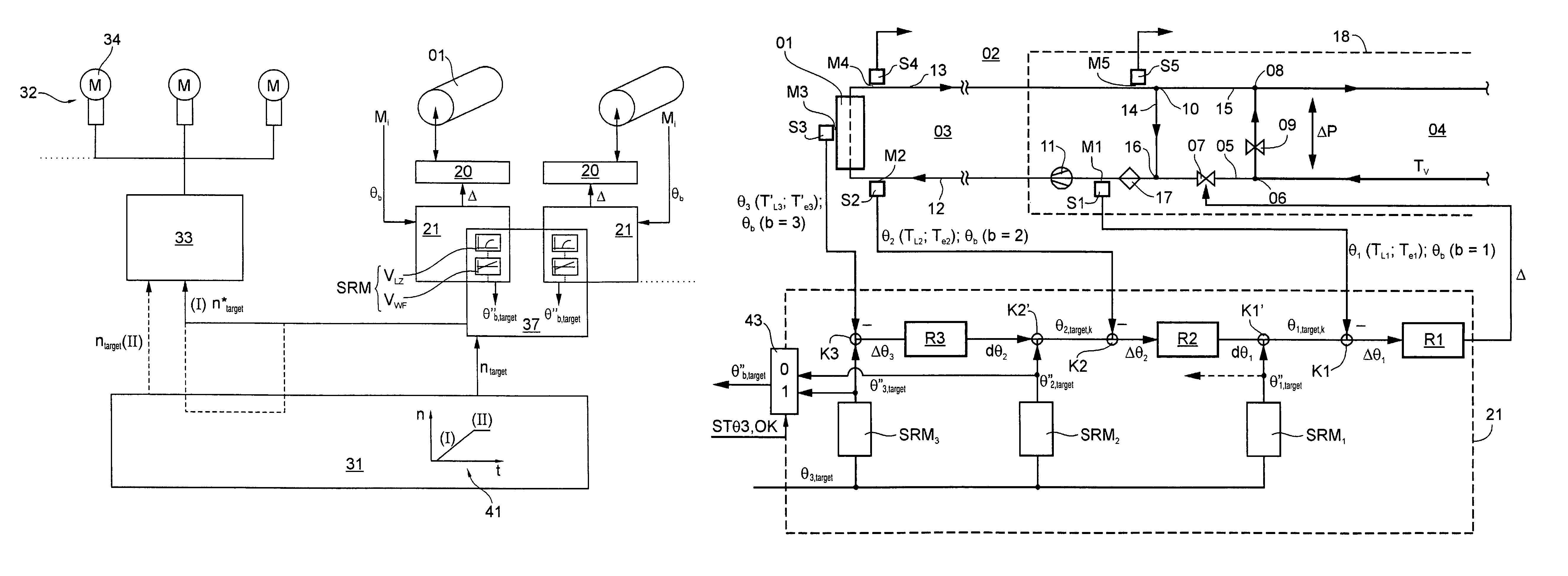
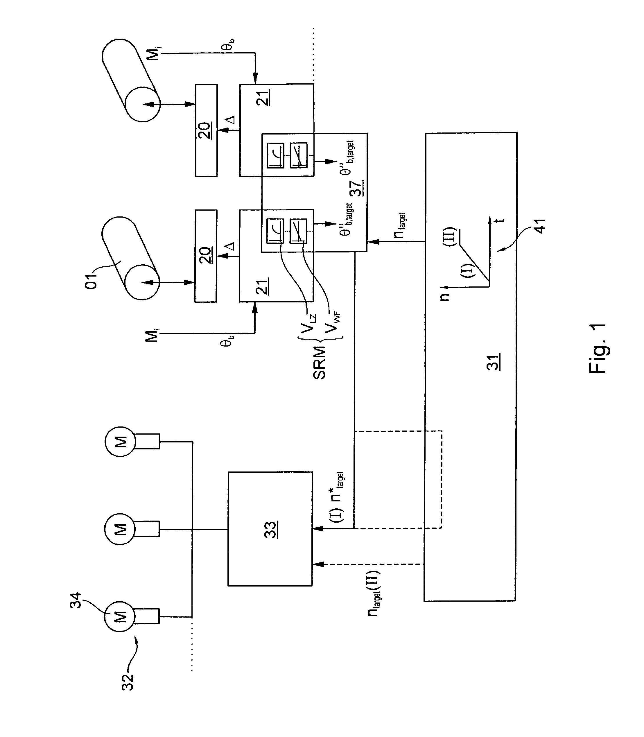
[0039]A printing press has at least one component, such as a roller 01, and in particular, has an ink guiding roller 01 of a printing couple, which is not specifically shown. This roller 01 can be configured as a roller 01 of an inking unit, for example, and particularly can be embodied as an anilox roller 01, or it can be configured as a cylinder 01 of the printing couple, for example, and particularly as a forme cylinder 01. The printing press further has a control level 31 with a control station, for example, and also with a press controller, through which a press speed “n”, identified here, for example, as the press rotational speed “n”, or the rotational speed “n” for short, is or can be prescribed in one or more drives 32, for example drive motors 32, such as, for example, with controller and motor 34) of the printing press as the target value for rotational speed ntarget. The predetermined value for the press rotational speed “n” is usually provided, as indicated by a dashed ...


PUM


Abstract

At least one rotating component of at least one printing unit is regulated to a target value for a temperature, representing the component temperature, by a temperature controller. At least one drive of an assembly of the printing machine is regulated or controlled, on the basis of a target value for a rotational speed prescribed by a command level, with respect to a rotational speed to be maintained. For at least an operating phase transient, relative to the rotational speed, a target value prescribed by the command level, is modified. This is done by considering at least one member of a route and / or a control model characterizing the temperature controller and / or by using a rule (F2(θ)) for a dependence of a rotational speed on a temperature. The modified target rotational speed serves as a prescribed value for the rotational speed of the drives.

Description

CROSS-REFERENCE TO RELATED APPLICATIONS[0001]This application is the U.S. national phase, under 35 U.S.C. 371, of PCT / EP2008 / 063474, filed Oct. 8, 2008; published as WO 2009 / 100783 A2 and A3 on Aug. 20, 2009, and claiming priority to DE 10 2008 000 271.2, filed Feb. 11, 2008, and to DE 10 2008 001 309.9, filed Apr. 22, 2008; the disclosures of which areFIELD OF THE INVENTION[0002]The present invention is directed to a method and to a device for controlling a printing press. At least one rotating component of at least one printing couple is controlled with respect to a target value for a temperature, which represents the component temperature, by the use of a temperature control device.BACKGROUND OF THE INVENTION[0003]A device and a method for controlling the temperature of a component in a printing press are known from DE 44 29 520 A1. The component is temperature controlled by the use of an at least partially circulating fluid. A control element, with which a mixing ratio can be ad...

Claims


Application Information

Patent Timeline
Patent Type & Authority Patents(United States)
IPC IPC(8): B41F5/00
CPCB41F13/22B41F31/002B41F33/12B41P2233/10
Inventor MULLER, KLAUS GEORG MATTHIASGABRIEL, GUNTHER EWALD
Owner KOENIG & BAUER AG
Why Eureka
Try Eureka