
Image bearing member, image forming apparatus, and process cartridge

a technology of image bearing and image forming apparatus, which is applied in the direction of electrographic process apparatus, corona discharge, instruments, etc., can solve the problems of abnormal images, photoreceptor replacement, and insufficient technology in the quick printing field, and achieves excellent durability, reduced voltage fluctuation, and high stability

Inactive Publication Date: 2011-03-10
RICOH KK
View PDF17 Cites 7 Cited by
  • Summary
  • Abstract
  • Description
  • Claims
  • Application Information

AI Technical Summary

Benefits of technology

[0036]For these reasons, the present inventors recognize that a need exists for an image bearing member that is free from production of abnormal images having image blur or stemming from filming, bad cleaning performance, etc., and reduces the fluctuation of the voltage at irradiated portions in one day and the intra-job fluctuation, resulting in a highly stable image bearing member having an excellent durability with constant image density and image consistency, and an image forming apparatus, and a process cartridge using the image bearing member.
[0037]Accordingly, an object of the present invention is to provide an image bearing member that is free from production of abnormal images having image blur or stemming from filming, bad cleaning performance, etc., and reduces the fluctuation of the voltage at irradiated portions in one day and the intra-job fluctuation, resulting in a highly stable image bearing member having an excellent durability with constant image density and image consistency, and an image forming apparatus, and a process cartridge using the image bearing member.

Problems solved by technology

However, these technologies are not sufficiently successful in the quick printing field because of problems related to abrasion resistance.
Moreover, even if abrasion resistance is not a fatal problem, other factors such as filming, attachment of foreign matter, and cleaning performance cause problems.
Therefore, the photoreceptors need replacing in a relatively short time.
Therefore, the surface of the photoreceptor is contaminated, resulting in production of abnormal images.
However, coating the surface of a photoreceptor with lubricant has a problem with sustainability of the effect.
That is, it is difficult to limit the contamination of a photoreceptor caused by repeated image formation processes such as charging, development, and cleaning for an extended period of time using only the lubricant contained in the photoreceptor from the beginning.
However, there are other problems to be solved to obtain a photoreceptor having improved durability.
This causes image density to fluctuate, and image blur occurs due to oxidized gas produced by a charger during charging.
However, known anti-oxidants have little effect in preventing image blur, and have a side effect of increasing the voltage at the irradiated portion.
Consequently, the voltage at the irradiated portion increases sharply, which degrades image density stability.
However, charge transport materials having a small ionization potential are generally inferior in stability and particularly susceptible to the effects of oxidized gas, resulting in occurrence of severe image blur.
Therefore, just using a transport material having a small ionization potential is not necessarily a solution to the problem.
However, occurrence of image blur caused by repetitive use for an extended period of time is not prevented.
However, although sufficient to solve the problems related to the durability of the photoreceptor that used to be required, these approaches fail to provide the durability required by the field of quick printing.
However, if the amount increases, the problem that the voltage at the irradiated portion increases over time inevitably arises.
This problem of fluctuation in the voltage at the irradiated portion in the image forming apparatus for use in the quick printing field is more serious when printing is resumed after one job than when images are output for a relatively long period of time.
However, when the intra-job fluctuation of the voltage at the irradiated portion is significant, its impact cannot be ignored or go unnoticed.
If the voltage fluctuates per output of several tens of images or several images, the correction of the voltage is difficult, which leads to a serious problem.
Moreover, often the same image pattern is output in a large quantity in one job particularly in the quick printing field.
If the intra-job fluctuation at the irradiated portion is significant in such a case, the image density changes, resulting in deterioration of image consistency.
By contrast, when outputting, for example, a full color image, not only the image density but also the color tone change, which creates an extremely serious problem.

Method used


Image

  • Image bearing member, image forming apparatus, and process cartridge
  • Image bearing member, image forming apparatus, and process cartridge
  • Image bearing member, image forming apparatus, and process cartridge

Examples


example 1

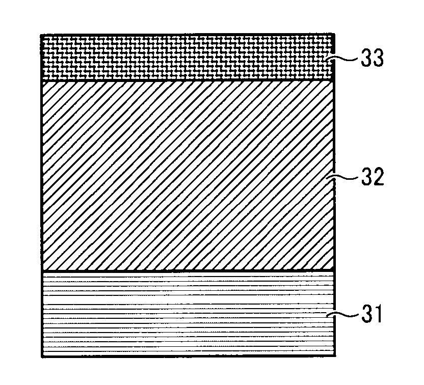
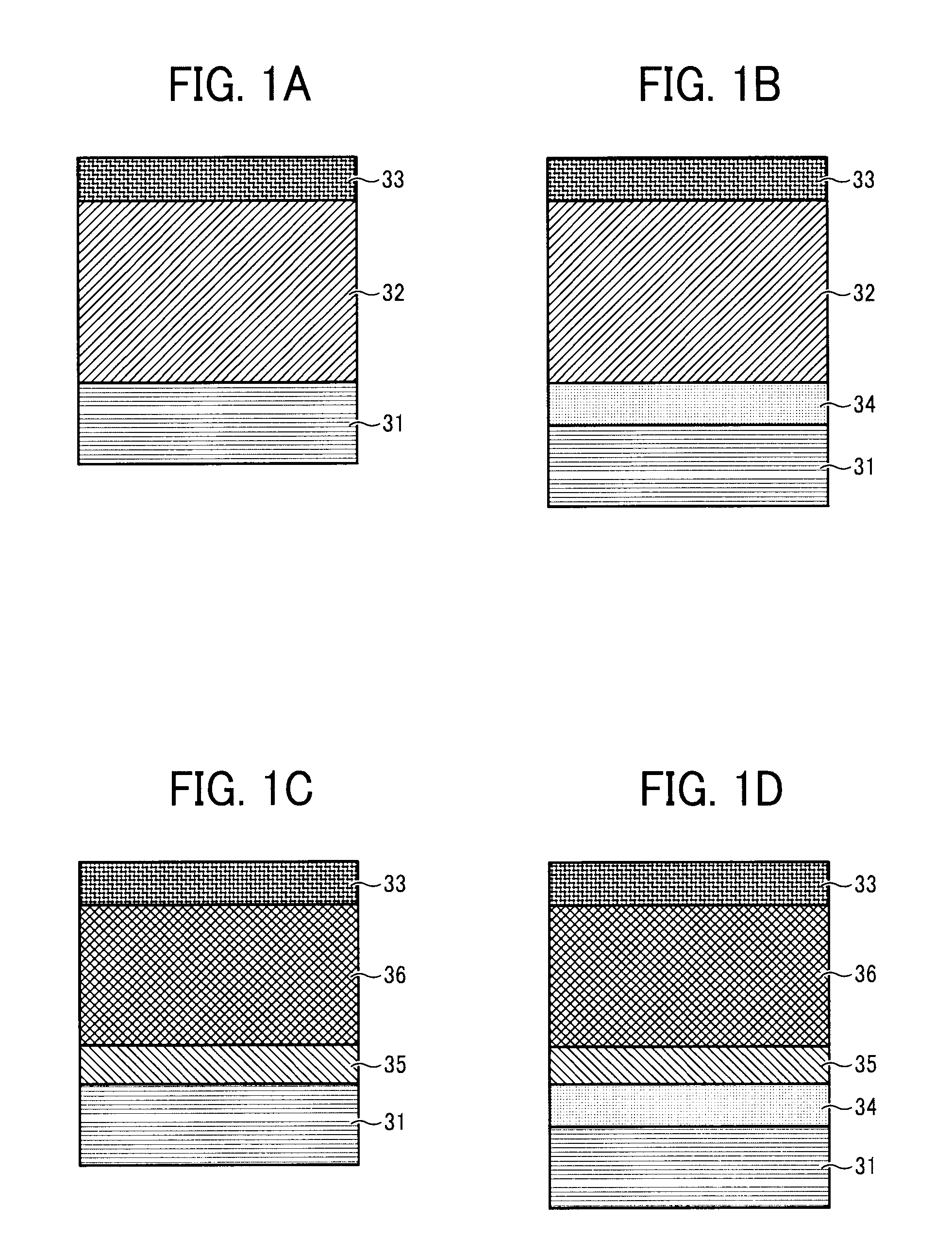
[0707]The liquid application for an intermediate layer, the liquid application of an undercoating layer, the liquid application of a charge generation layer, and the liquid application of a charge transport layer having the following recipes are applied to an aluminum cylinder having an outer diameter of 60 mum, in that order, by a dip coating method followed by drying in an oven to obtain an intermediate layer having a thickness of about 0.5 μm, an undercoating layer having a thickness of about 2.5 μm, a charge generation layer having a thickness of about 0.2 μm, and a charge transport layer having a thickness of about 22 μm.

[0708]The drying condition for each layer is: 130° for 10 minutes for the intermediate layer; 130° C. for 20 minutes for the undercoating layer; 90° C. for 20 minutes for the charge generation layer; and 120° C. for 20 minutes for the charge transport layer.

Liquid Application for Intermediate LayerN-methoxy methylated nylon (FR-101, 5 partsmanufactured by Namar...

example 2

[0716]The image bearing member of Example 2 is manufactured in the same manner as in Example 1 except that the diamine compound represented by the illustrated diamine compound no. 7 is changed to the diamine compound represented by the illustrated diamine compound no. 3 having a molecular weigh of 194.32.

example 3

[0717]The image bearing member of Example 2 is manufactured in the same manner as in Example 1 except that the diamine compound represented by the illustrated diamine compound no. 7 is changed to the diamine compound represented by the illustrated diamine compound no. 5 having a molecular weigh of 372.56.


PUM


Abstract

An image bearing member including an electroconductive substrate, a photosensitive layer overlying the electroconductive substrate, and a protection layer overlying the photosensitive layer, the photosensitive layer containing a diamine compound represented by the chemical structure 1, more of the diamine compound being disposed on the photosensitive layer side than the surface side relative to the midpoint in a depth direction of the protection layer:where X represents a substituted or non-substituted arylene group, or a compound represented by a chemical structure 2:where R represents a hydrogen atom, an alkyl group having 1 to 4 carbon atoms, or an alkoxy group having 1 to 4 carbon atoms,where A1, A2, A3, and A4 independently represent an alkyl group having 1 to 4 carbon atoms, a substituted or non-substituted aryl group, or —CH2(CH2)mZ, where Z represents a substituted or non-substituted aryl group, a substituted or non-substituted cycloalkyl group, and a substituted or non-substituted heterocycloalkyl group, and m represents 0 or 1, and where B1 and B2 represent —CH2—, —CH2CH2—, —CH2—Ara—, —Ara—CH2—, —CH2CH2—Ara—, and —Ara—CH2CH2—, and Ara represents a substituted or non-substituted arylene group.

Description

BACKGROUND OF THE INVENTION[0001]1. Field of the Invention[0002]The present invention relates to an image bearing member, and an image forming apparatus and a process cartridge using the image bearing member. The image forming apparatus and the process cartridge are widely applicable to photocopiers, facsimile machines, laser printers, direct digital platenmakers, etc.[0003]2. Discussion of the Background[0004]In recent years, image forming apparatuses such as laser printers, digital photocopiers that employ an electrophotographic system have been improved with regard to image quality and reliability thereof and are now widely diffused.[0005]Such image forming apparatuses use an image bearing member, the surface of which is charged and irradiated with light to form latent electrostatic images thereon, followed by development to obtain a visual image. This image bearing member may be a photoreceptor or photoconductor.[0006]The image bearing members are classifiable generally into ino...

Claims


Application Information

Patent Timeline
IPC IPC(8): G03G15/00G03G21/18
CPCG03G5/0614G03G5/0672G03G5/071G03G5/0683G03G5/0696G03G5/0679G03G5/06144G03G5/061473G03G5/072G03G5/0732G03G5/074
Inventor TAMOTO, NOZOMUHIROSE, MITSUAKINAKAMORI, HIDEO
Owner RICOH KK
Learn More