
Carrier, two-component developer comprising the same, and developing device and image forming apparatus using the two-component developer

a two-component developer and carrier technology, applied in the direction of developers, instruments, optics, etc., can solve the problems of resin layer wear, difficult stabilization of toner charge amount, and complicated development device, and achieve the effect of stable formation

Inactive Publication Date: 2009-12-17
SHARP KK
View PDF12 Cites 6 Cited by
  • Summary
  • Abstract
  • Description
  • Claims
  • Application Information

AI Technical Summary

Benefits of technology

[0012]It is an object of the invention to provide a carrier having good dispersibility of a charge control agent contained in a resin layer and having no lot difference, a two-component developer capable of inhibiting the unevenness in the charge amounts due to the lot difference by comprising the carrier, and a developing device and image forming apparatus, which is capable of stably forming an image having a constant image density over a long period of time by employing the two-component developer.

Problems solved by technology

However, the one-component developer has disadvantages such that stabilization of a charge amount of the toner is not easy.
The two-component developer has a disadvantage that an agitation mechanism and the like to evenly mix a toner and a carrier are required, which makes the developing device more complicate.
However, in the case of using a two-component developer comprising the carrier as disclosed in JP-A 9-6054 having the surface coated with a thermosetting silicone resin to form an image, the resin layer starts to wear out from the 30000th sheet due to the agitation in the image forming apparatus, the charge amount lowers, and fogging occurs.
However, since the variation in the charge amounts is generated due to the lot difference of the carrier, and accordingly, it was found that a constant image quality density cannot be maintained over a long period of time, even by taking such a measure.
Although a concrete mechanism has not been clarified, it is presumed that under a heating condition for the thermosetting treatment of the silicone resin, the charge control agents are molten, which causes them to aggregate with each other or bleed on the carrier surface thereby changing the dispersion state, the dispersibility deteriorates, and accordingly the unevenness in the charge amounts occurs due to the lot difference of the carrier.
Further, it is believed that a fact that a part of the charge control agents is thermally decomposed and is not crystallized upon cooling after the thermosetting treatment, but is rendered to be amorphous, and the like is also a cause of the unevenness in the charge amounts due to the lot difference of the carrier.

Method used


Image

  • Carrier, two-component developer comprising the same, and developing device and image forming apparatus using the two-component developer
  • Carrier, two-component developer comprising the same, and developing device and image forming apparatus using the two-component developer
  • Carrier, two-component developer comprising the same, and developing device and image forming apparatus using the two-component developer

Examples


example 1

[0217](Preparation of Core Particle)

[0218]As the raw materials of a ferrite, a slurry containing 50 mol % of iron oxide (manufactured by KDK Corporation), 35 mol % of manganese oxide (manufactured by KDK Corporation), 14.5 mol % of magnesium oxide (manufactured by KDK Corporation), and 0.5 mol % of strontium oxide (manufactured by KDK Corporation) and having water as a medium was pulverized with a ball mill for 4 hours. This slurry was dried in a spray drier, and the particle of the resulting spherical particle was tentatively fired in a rotary kiln at 930° C. for 2 hours. This tentatively fired powder was dispersed in water, and finely pulverized to an average particle size of 2 μm or less in a wet pulverizer (using a steel ball as a pulverizing medium). 2% by weight of PVA was added to this slurry, granulated by a spray dryer, dried, and subjected to main firing in an electric furnace at a temperature of 1100° C. and an oxygen concentration of 0 volume % for 4 hours. Then, perform...

example 12

[0224](Primary Coating)

[0225]A coating solution for primary coating containing a positively chargeable charge control agent was prepared by dissolving 100 parts by weight of a dimethyl silicone resin (manufactured by Toshiba Silicones), 5 parts by weight of Compound 1 (melting point: 177.3° C.) as a positively chargeable charge control agent, and 5 parts by weight of octylic acid as a curing agent in 890 parts by weight of a mixed solution of toluene and methanol (toluene:methanol=10:1). In a coating device for a dipping method (product name: Versatile Mixer NDMV type, manufactured by DALTON CORPORATION), the core particle was coated with a thermosetting silicone resin containing a positively chargeable charge control agent by dipping 100 parts by weight of the core particle obtained in Example 1 (preparation of a core particle) in 30 parts by weight of the coating solution for primary coating. Then, by completely removing the solvent from the coated core particle by evaporation, a ...

examples 13 to 22

[0228]The carriers of Examples 13 to 22 were prepared in the same manner as in Example 12, except that at least one of the types of the charge control agent, a temperature upon thermosetting treatment, or a time upon thermosetting treatment was changed into one as shown in Table 2.

TABLE 2Primary coatingSecondary coatingCharge control agentCharge control agentCondition forCarrierAdditionAdditionthermosetting treatmentVolumeMeltingamountMeltingamountThermosettingaverageSaturationpoint(parts bypoint(parts bytemperatureThermosettingparticle sizemagnetizationType(° C.)weight)Type(° C.)weight)(° C.)time (minutes)(μm)(emu / g)Example 12Compound 11775Compound 62055150604665Example 13Compound 21675Compound 62055140604665Example 14Compound 31755Compound 62055145604665Example 15Compound 41435Compound 62055110604665Example 16Compound 51855Compound 62055155604665Example 17Compound 11775Compound 62055170304665Example 18Compound 11775Compound 620551101204665Example 19Compound 31755Compound 620551653...


PUM


Abstract

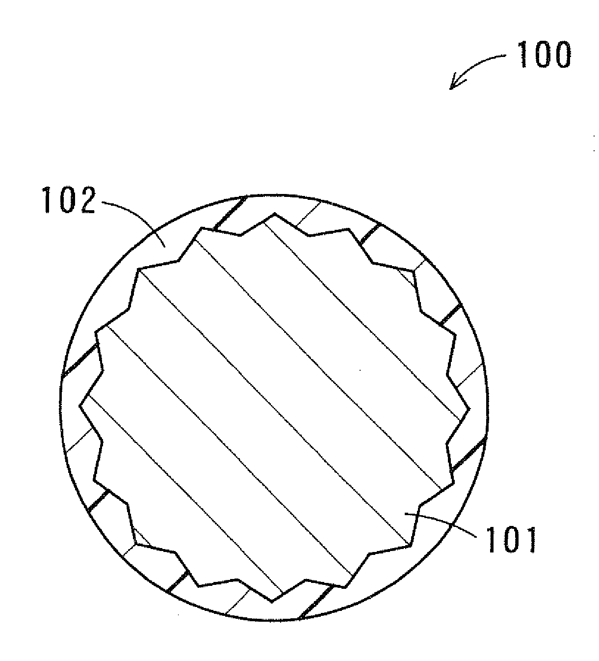
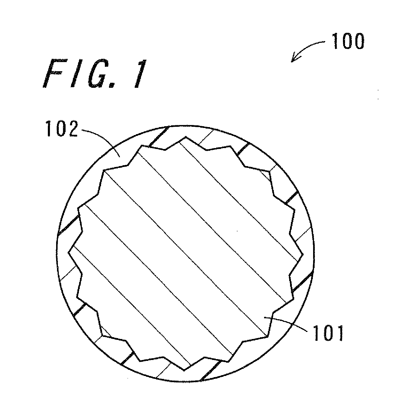
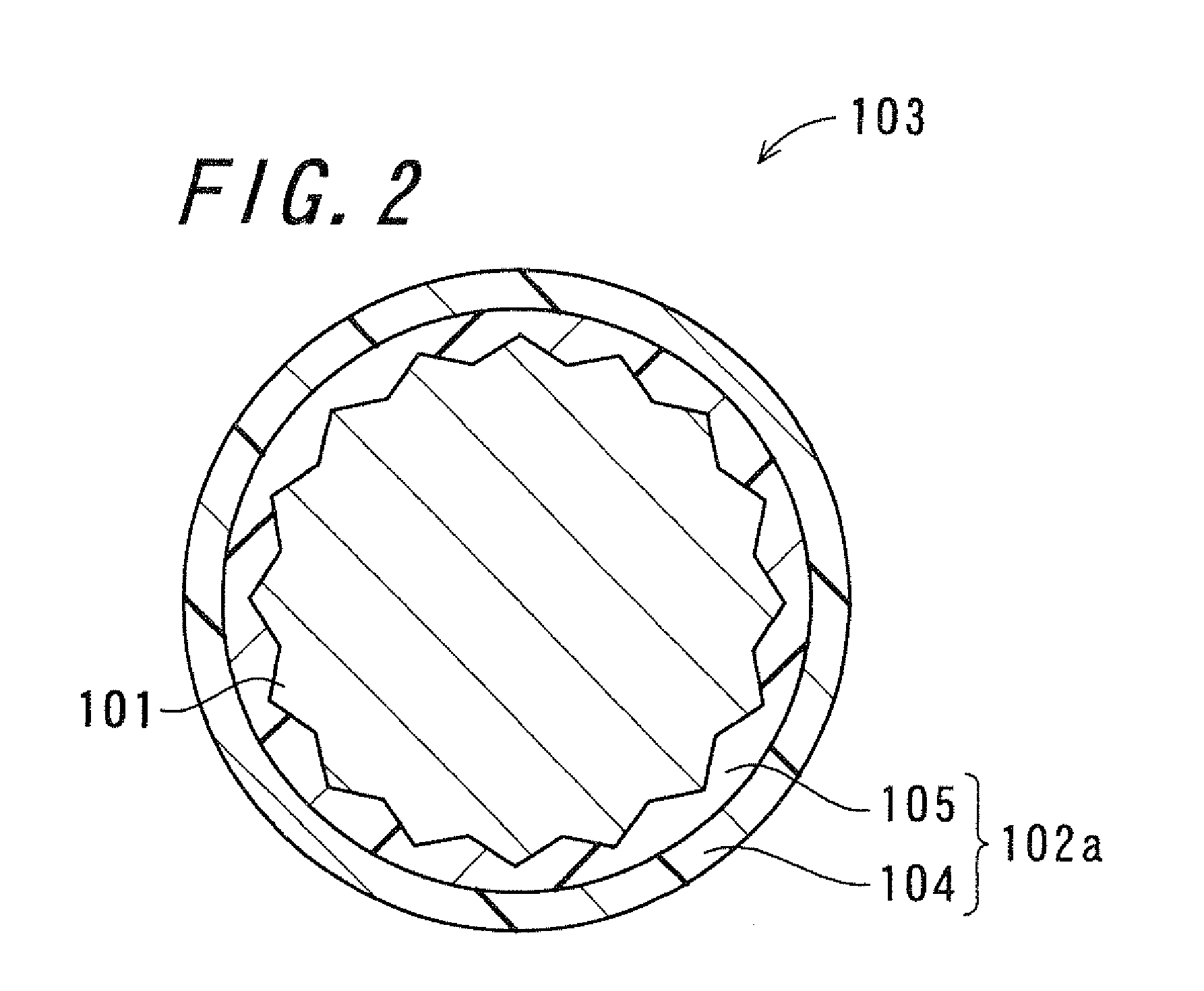
A carrier has a thermosetting silicone resin layer formed of a core particle and a thermosetting silicone resin on the surface of the core particle, and the thermosetting silicone resin layer is formed by subjecting a thermosetting silicone resin to a thermosetting treatment at a temperature lower than the melting point of a charge control agent contained in the thermosetting silicone resin layer, and includes an inner region which contains a positively chargeable charge control agent and an outer region which does not contain any positively chargeable charge control agent. The two-component developer containing the carrier as described above is charged into a developing device in an image forming apparatus to form an image.

Description

CROSS-REFERENCE TO RELATED APPLICATION[0001]This application claims priority to Japanese Patent Application No. 2008-155976, which was filed on Jun. 13, 2008, the contents of which are incorporated herein by reference in their entirety.BACKGROUND OF THE INVENTION[0002]1. Field of the Invention[0003]The present invention relates to a carrier, a two-component developer comprising the same, and a developing device and an image forming apparatus which employ the two-component developer.[0004]2. Description of the Related Art[0005]An image forming apparatus employing an electrophotographic system performs, for example, a charging step, an exposure step, a developing step, a transfer step, a cleaning step, a charge removing step, and a fixing step to form an image. In the step for forming an image, for example, a surface of a photoreceptor driven for rotation by a charging device is uniformly charged, and a laser beam is irradiated onto the surface of the photoreceptor charged by an expos...

Claims


Application Information

Patent Timeline
Patent Type & Authority Applications(United States)
IPC IPC(8): G03G9/00
CPCG03G9/1138G03G9/1136
Inventor HIRATA, KANAKOTAKATSUKA, KAZUKINISHIKAWA, TORU
Owner SHARP KK
Learn More