Method and device for producing three-dimensional molded parts and corresponding molded part

a three-dimensional molded and corresponding technology, applied in the field of three-dimensional molded parts and corresponding molded parts, can solve the problems of difficult recycling of pu foam, reduced production efficiency, and high cost, and achieve the effect of reducing the production time of individual molded parts, good reproducibility, and optimizing the production of molded parts

Inactive Publication Date: 2007-01-11
FIBER ENG
View PDF9 Cites 7 Cited by
  • Summary
  • Abstract
  • Description
  • Claims
  • Application Information

AI Technical Summary

Benefits of technology

[0025] In a preferred embodiment of the device according to the invention, at least one temporary auxiliary top mold can be set on the bottom mold instead of the top mold. The use of temporary auxiliary top molds has proven to be advantageous when molded parts of different densities or with different layers are to be produced. The temporary auxiliary top mold is set on the bottom mold and filled. It can then be exchanged for the top mold. If the cavity of the auxiliary top mold differs from the volume of the top mold, the preform can still be compacted before it solidifies into a molded part. The compression can also be limited just to local regions. However, the density distribution has very good reproducibility.
[0026] Furthermore, a device in which a rotary table with four processing stations is used is advantageous. In one blow in station, fiber material is blown into the mold. A heating station is used for heating the mold. The cooling of the molded part is performed in a cooling station. In a removal station, the mold can be opened and the molded part removed. The use of such a rotary table with at least four stations features the advantage that each station is formed especially for the processing steps to be performed there. The individual stations can be formed such that the production of the molded parts can be optimized. By using a rotary table with several stations, several molded parts can be produced simultaneously, with each molded part being located in a different stage of production. Therefore, the production time of an individual molded part can be significantly reduced.
[0027] A molded part, which was produced according to the method according to the invention, distinguishes itself through regions of different density. The various regions are clearly delimited from each other in space. Either various layers or also partial areas of different density can be generated. The areas with higher density can be provided at arbitrary positions of the molded part, independent of the geometry of the molded part. In this way, areas with lower density can also be realized in which the requirements for sound insulation in the molded part play only a subordinate role. The molded part then features a low weight overall.

Problems solved by technology

However, this is relatively expensive, because this type of foam is produced on the basis of crude oil.
In addition, PU foam is also hard to recycle.
When burned, it emits poisonous vapors.
Molded parts made of conventional fiber mats, which are produced from fiber materials by rollers, are only suitable to a limited degree.
Fiber mats can only be used for weakly deformed parts.
Also, due to the rolling method, they do not exhibit a uniform density distribution.
Therefore, they frequently do not correspond to the geometrical and acoustic requirements placed on such special molded parts.
A disadvantage of this method is that partial flocking cannot be performed precisely, and thus, in particular, a local increase in density is not possible.
Likewise, it is possible only with difficulty to reduce the weight of the entire molded part, such that certain acoustically non-critical areas feature a smaller density.
Due to the expensive machine use times, the costs of the molded part are rather high.
However, this method has the disadvantages described above.

Method used


Image

  • Method and device for producing three-dimensional molded parts and corresponding molded part
  • Method and device for producing three-dimensional molded parts and corresponding molded part
  • Method and device for producing three-dimensional molded parts and corresponding molded part

Examples


Embodiment Construction

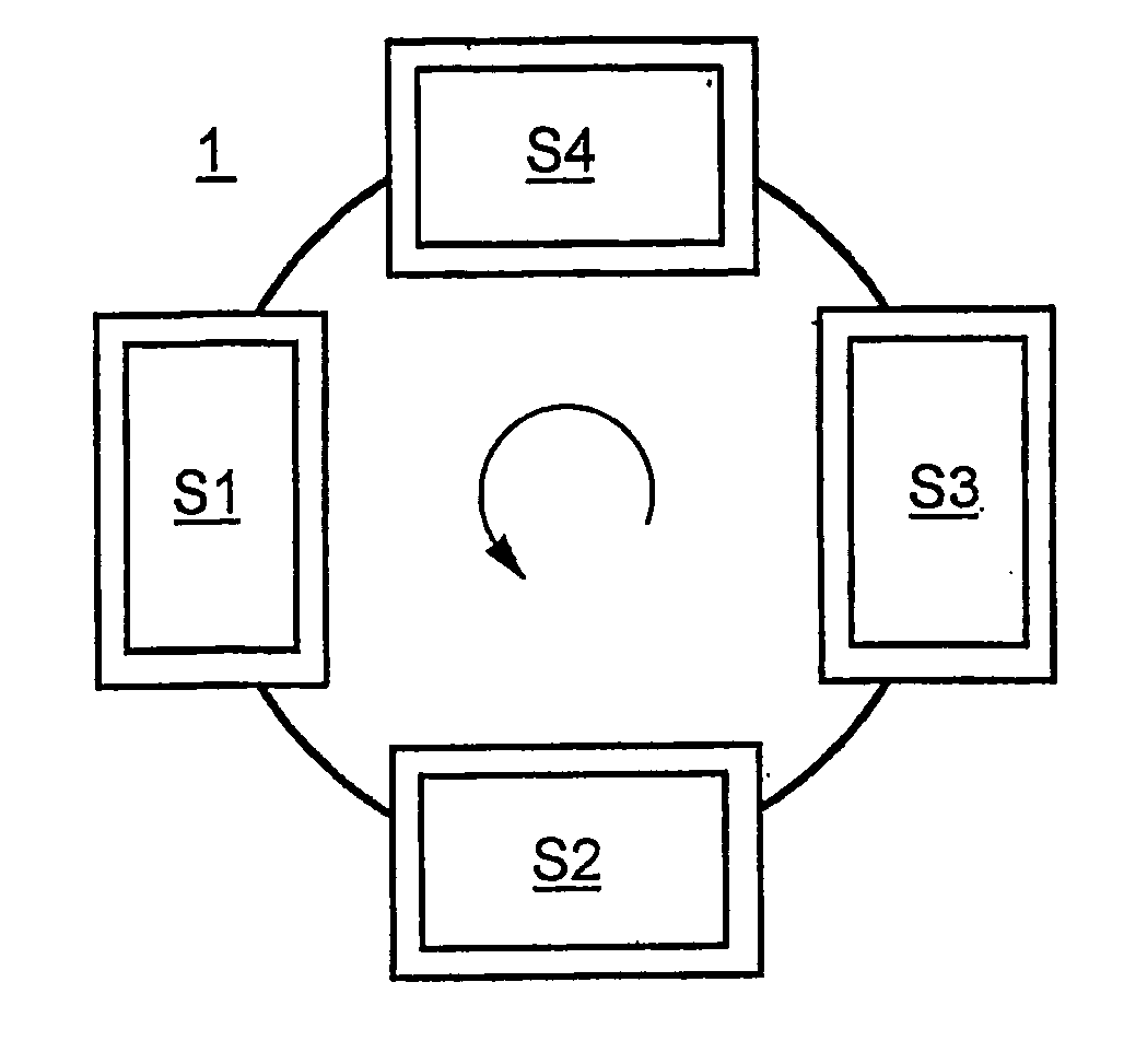
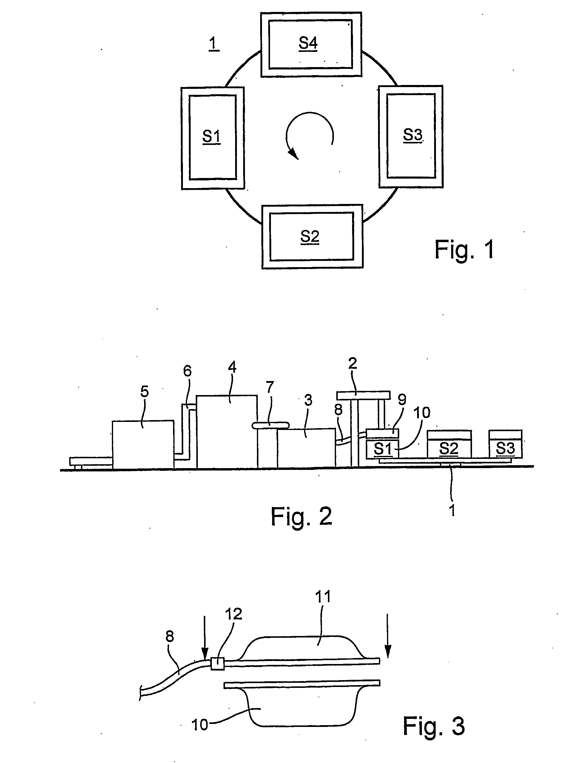
[0032] The device shown in FIG. 1 comprises a blow in station S1, a heating station S2, a cooling station S3, and a removal station S4. The stations S1-S4 are arranged on a rotary table 1, which can rotate counterclockwise. In the blow in station S1, fiber material is blown into a closed mold until a preform is formed. In the heating station S2, the production mold is heated so that the preform solidifies into a molded part. In the cooling station S3, the production mold is cooled. In the removal station S4, the mold is opened so that the produced part can be removed.

[0033]FIG. 2 shows a complete system for producing molded parts, which comprises the rotary table 1, a supply device 2 for supplying and changing molds, a fan 3, a fiber storage device 4, and a lump opener 5. From rotary table 1, the blow in station S1, the heating station S2, and the cooling station S3 can be seen.

[0034] Premixed fiber lumps, which are used as raw material, are fed to the lump opener 5 and there chop...


PUM

PropertyMeasurementUnit
air pressureaaaaaaaaaa
densityaaaaaaaaaa
stiffnessaaaaaaaaaa

Abstract

A method for producing three-dimensional parts made of fiber material using a mold, comprising a bottom mold, the inner side of which determines the contour of the bottom side of the molded part and a top mold whose inner side determines the contour of the top side of the molded part. The bottom mold and/or the top mold have holes enabling the passage of air. Fibers are blown into the interior of the closed mold with the aid of an air current and are deposited in the inner sides of the bottom mold and the top mold, whereby a blank of fiber material is formed, the fibers bound together by a bonding agent, whereupon the blank is hardened into a molded part. A device for the production of three-dimensional molded parts comprises a mold having at least one inlet hole for blowing in the fiber material. The molded part has areas with different thickness.

Description

BACKGROUND OF THE INVENTION [0001] Three-dimensional molded parts made of fiber material are used, in particular, in the automotive industry. These molded parts are used for sound insulation. They are used, for example, as door linings, rear package shelves, and vehicle ceilings. Likewise, the floor and the walls connecting the passenger compartment to the trunk space and also the passenger compartment to the engine space are lined with sound-insulating molded parts. Here, one-piece parts should be used as much as possible. The car-body plates are deformed greatly and irregularly in terms of stiffness and material savings. They feature receptacles for additional components of the vehicle and passages, for example, for cable channels and the steering-wheel column. The molded parts that are used for sound insulation must be adapted to these strongly three-dimensionally shaped chassis parts. [0002] Three-dimensional molded parts for sound insulation, so-called acoustic parts, with uneq...

Claims


Application Information

Patent Timeline
Patent Type & Authority Applications(United States)
IPC IPC(8): B27N1/00B29C70/30
CPCB29L2031/3005B29C70/305
Inventor FORSTER, EGON
Owner FIBER ENG
Why Eureka
Try Eureka