Eureka AIR delivers breakthrough ideas for toughest innovation challenges, trusted by R&D personnel around the world.

Annular sealing assembly for insertion between two mechanical members in relative motion, in particular a linear reciprocating motion, as a rod and the relative guiding seat of a mono-tube shock-absorber

a technology of annular sealing and mechanical members, which is applied in the direction of shock absorbers, instruments, analogue processes for specific applications, etc., can solve the problems of poor performance, incomplete assembly of type 1, and worsening performan

Active Publication Date: 2012-03-06
AB SKF
View PDF18 Cites 13 Cited by
  • Summary
  • Abstract
  • Description
  • Claims
  • Application Information

AI Technical Summary

Benefits of technology

[0005]It is an object of the present invention to provide a sealing assembly for insertion between two mechanical members in relative motion, particularly but not exclusively a linear reciprocating motion, as a rod and relative guide seat of a shock absorber, designed to eliminate the drawbacks of the known art, and which, in particular, is specifically designed for use in one-pipe shock absorbers and anyway between organs operating at very low temperatures, well below minus 15° C., and more generally in a wide range of temperatures, e.g. between −40° C. and +200° C.
[0006]In particular, it is an object of the invention to provide a sealing assembly of the above type, which also performs excellently at very low temperature, is extremely easy to assemble, is cheap to produce and assemble, and is compact.
[0012]The sleeve portion of the reinforcing structure thus cooperates elastically, in use, with the sealing lip, on the one hand to limit maximum radial deformation of the sealing lip, and, on the other, to provide mechanical support which, by virtue of the geometry adopted, surprisingly prevents the fall-off in performance, typical of known sealing assemblies for one-pipe shock absorbers of the type shown in FIG. 1, at very low operating temperatures below minus 15° C.
[0013]At the same time, using the same mix for the sealing lip (FKM), performance in not particularly low temperature conditions remains substantially unchanged, and, above all, the sealing assembly is much more compact, both axially and radially, and much easier to assemble, thus enabling considerable saving.

Problems solved by technology

Known sealing assemblies of the type shown in FIG. 1 are however not completely satisfactory, by being relatively bulky and relatively complicated to assemble on account of the number of connected parts involved, and by having worsening performances with temperature decreasing.

Method used


Image

  • Annular sealing assembly for insertion between two mechanical members in relative motion, in particular a linear reciprocating motion, as a rod and the relative guiding seat of a mono-tube shock-absorber
  • Annular sealing assembly for insertion between two mechanical members in relative motion, in particular a linear reciprocating motion, as a rod and the relative guiding seat of a mono-tube shock-absorber
  • Annular sealing assembly for insertion between two mechanical members in relative motion, in particular a linear reciprocating motion, as a rod and the relative guiding seat of a mono-tube shock-absorber

Examples


Embodiment Construction

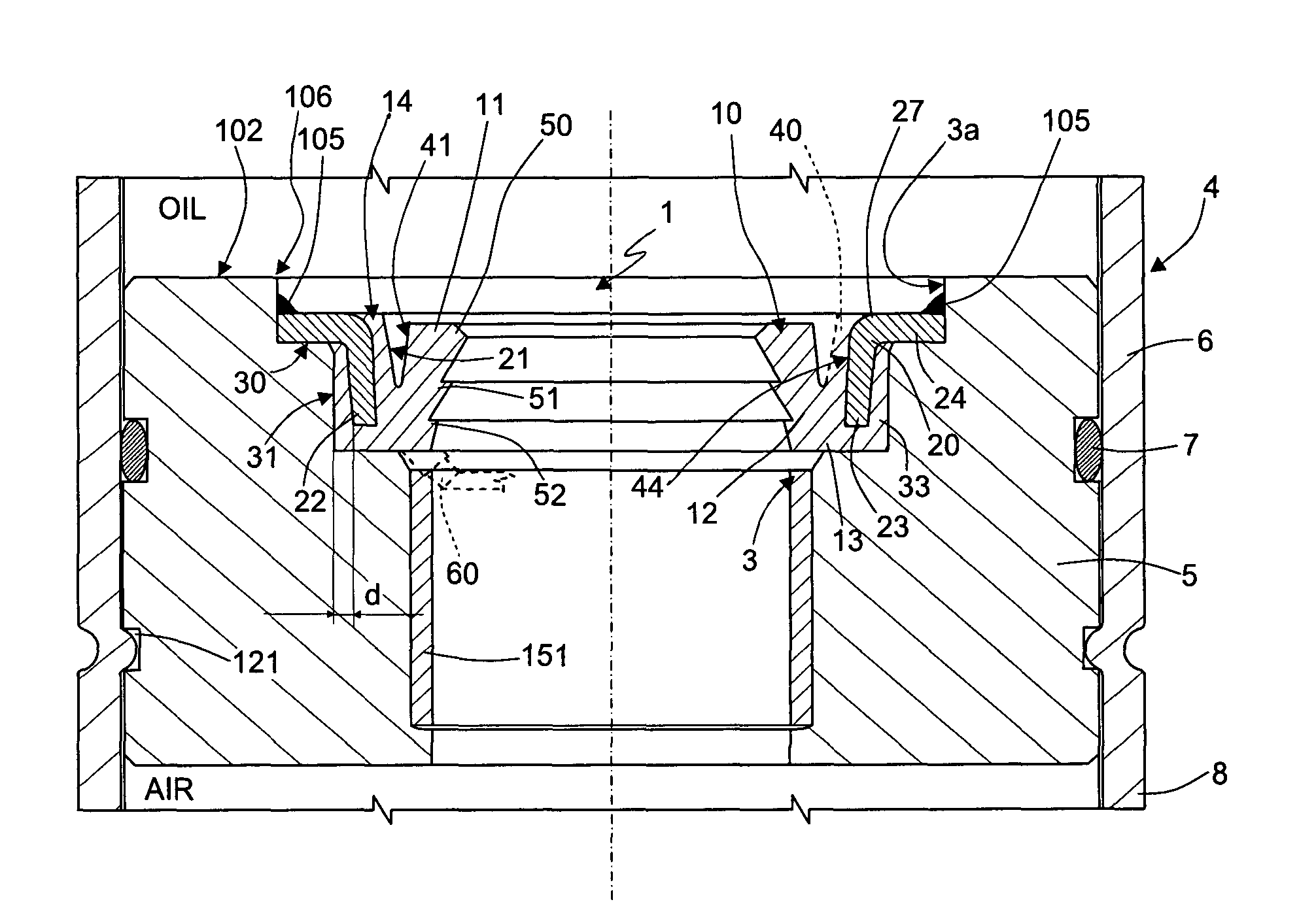
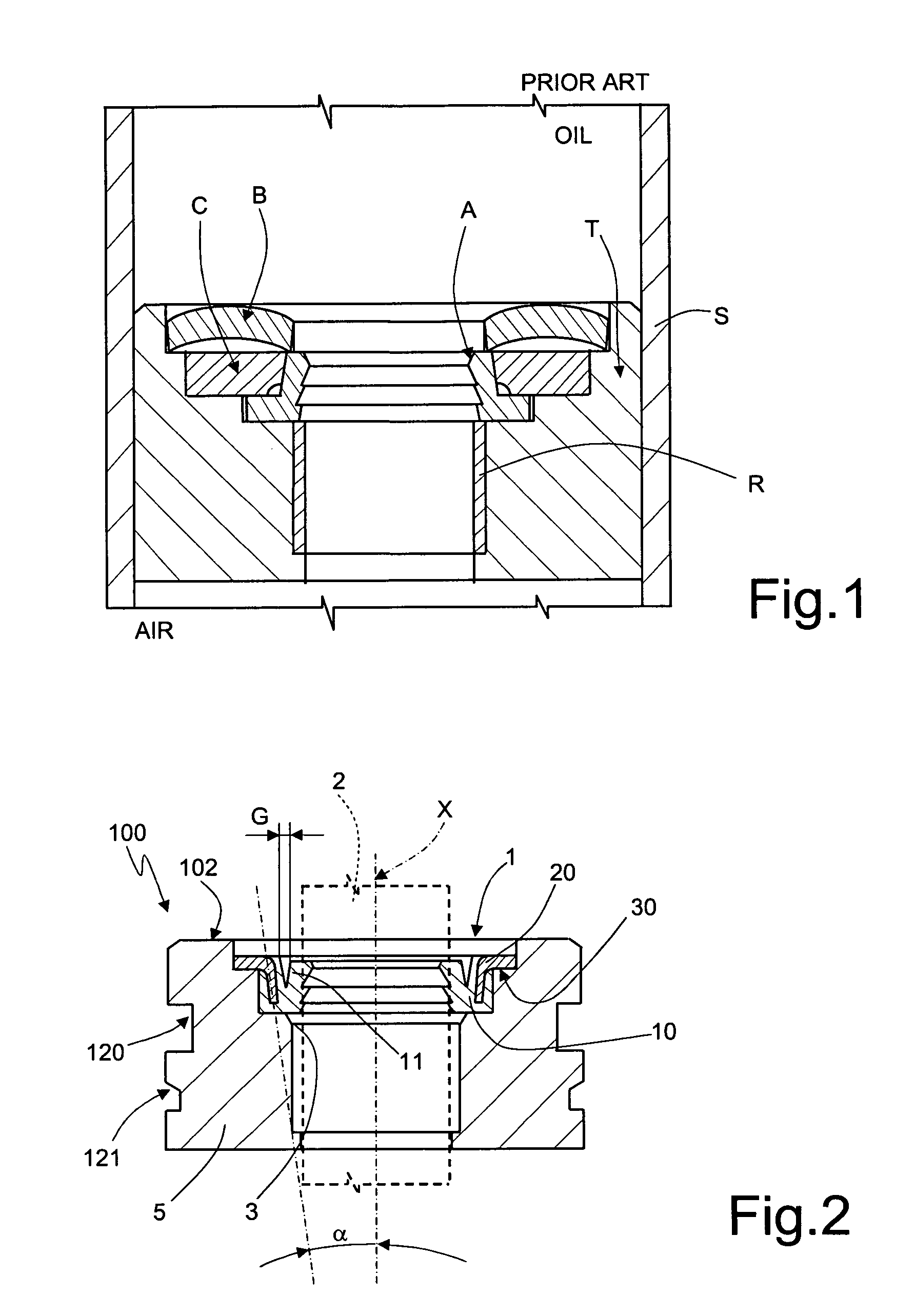
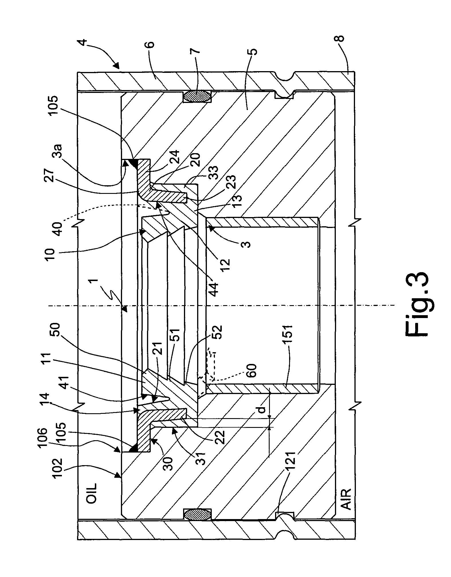
[0023]Number 1 in FIGS. 2 and 3 indicates a sealing assembly for insertion between two mechanical members which are in relative motion under normal operative conditions; in the non limiting embodiment illustrated, the mechanical members are subject to a linear reciprocating motion and in particular consist in a shock absorber rod 2 and a relative guide seat 3 of a one-pipe shock absorber 4, only an end portion of which is shown in FIG. 3. Seat 3 is formed in known manner through a substantially known bush 5, which is driven, in use, in fluidtight manner inside a body 6 of shock absorber 4, e.g. by means of a sealing ring 7 and by riveting or caulking an end 8 of one-pipe body 6 of shock absorber 4 in known manner to bush 5, e.g. inside an annular outermost radial groove 121 of bush 5. The latter is also provided with a radially innermost known guiding liner 151 for rod 2 also having anti-friction capacity, lining the inner side of guide seat 3.

[0024]Sealing assembly 1 (FIG. 3) is ax...


PUM


Abstract

A sealing assembly including a sealing ring made of elastomeric material and having, integrally in one piece, at least one elastically deformable, annular sealing lip, at least part of which projects axially from and radially inwards of the sealing ring, from a respective root portion adjacent to a first axial end of the sealing ring, and towards a second axial end, opposite the first, of the sealing ring; and an annular reinforcing structure made of material which is elastically deformable but relatively much more rigid than the elastomeric material of the sealing ring and relative lip, and at least partly embedded in the sealing ring; wherein the reinforcing structure extends at least partly in an axial direction, at least partly alongside but on the opposite side to the sealing lip; the sealing lip being designed to define, when undeformed, a predetermined radial clearance between itself and a radially inner lateral wall of the sealing ring.

Description

[0001]The present invention relates to an annular sealing assembly of the type inserted between two mechanical members in relative motion, in particular a linear reciprocating motion, as a rod and relative guide seat of a “mono-tube” or “one-pipe” shock absorber.BACKGROUND OF THE INVENTION[0002]One-pipe hydraulic shock absorbers, widely used in the automotive and other industries, operate under relatively high hydraulic pressures, on average about 20 bars, with peaks of as high as 100 bars. To cope with such high operating pressures, sealing of the pressurized oil opposing the shock absorber piston—sealing which takes place between the shock absorber rod and the rod guide seat normally formed through a bush fitted in fluidtight manner inside the shock absorber body—is performed by a sealing assembly of the type shown in FIG. 1, which comprises at least three members: a conical rubber pad A fitted to a bush T and having a sealing lip, which pad constitutes the actual sealing member s...

Claims


Application Information

Patent Timeline
Patent Type & Authority Patents(United States)
IPC IPC(8): F16F9/36
CPCF16F9/36F16J15/3252G06F17/5018G06T17/20G06F30/23
Inventor PASINO, ROBERTO
Owner AB SKF
Why Eureka
Eureka Blog
Learn More