Terminal fitting connecting structure

a technology of connecting structure and terminal fitting, which is applied in the direction of coupling contact member, coupling device connection, electric discharge lamp, etc., can solve the problems of large insertion load received, achieve simple structural change, reduce insertion force, and prevent shaking and twisting movement of the tab.

Inactive Publication Date: 2012-03-06
SUMITOMO WIRING SYST LTD
View PDF9 Cites 55 Cited by
  • Summary
  • Abstract
  • Description
  • Claims
  • Application Information

AI Technical Summary

Benefits of technology

[0009]When being at least partly inserted into the connecting tube portion of the female terminal, the tab of the male terminal is pushed in while resiliently displacing the resilient contact piece. First, as the base end edge of the inclined surface located more forward passes the corresponding contact portion, a relatively small first peak of an insertion force is reached. Thereafter, as the base end edge of the inclined surface located more backward passes the corresponding contact portion, a similarly relatively small second peak of an insertion force is reached. In other words, in the case of inserting the tab, the insertion force is distributed to have relatively small peaks at two positions, with the result that the insertion force is reduced. Further, a reduction in the insertion force is dealt with by a simple structural change of making the positions of the respective base end edges different in forward and backward direction.
[0020]To reduce an overall level of the insertion force of the tab, it is more effective if the inclination of the inclined surfaces is more moderate and the lengths of the inclined surface are longer. On the other hand, the length of the tip portion projecting from the rear edge of the connecting tube when the tab is inserted by a proper amount is limited, for example, to avoid interference with a core of a wire connected to a barrel by crimping. Here, if inclined surfaces are formed beyond the projecting area of the tip portion of the tab, base ends of the inclined surfaces engage with the excessive deformation preventing portions provided on the rear edge of the connecting tube. Therefore a function of preventing shaking and twisting movements of the tab cannot be fulfilled sufficiently.
[0021]In contrast, the upper and lower inclined surfaces are formed only in the projecting area of the tip of the tab while being inclined as moderately as possible. Thus, the flat surfaces of the tab face the excessive deformation preventing portions on the rear edge when the tab is inserted by the proper amount. As a result, the function of preventing shaking and twisting movements of the tab can be fulfilled reliably.
[0022]Accordingly, it is possible to reduce an insertion force by a simple structural change of the male terminal.

Problems solved by technology

Thus, a large insertion load is received during a connecting operation, i.e. a large insertion force (about 75N) is necessary, which has been a problem in ensuring a smooth connecting operation.

Method used


Image

  • Terminal fitting connecting structure
  • Terminal fitting connecting structure
  • Terminal fitting connecting structure

Examples


Embodiment Construction

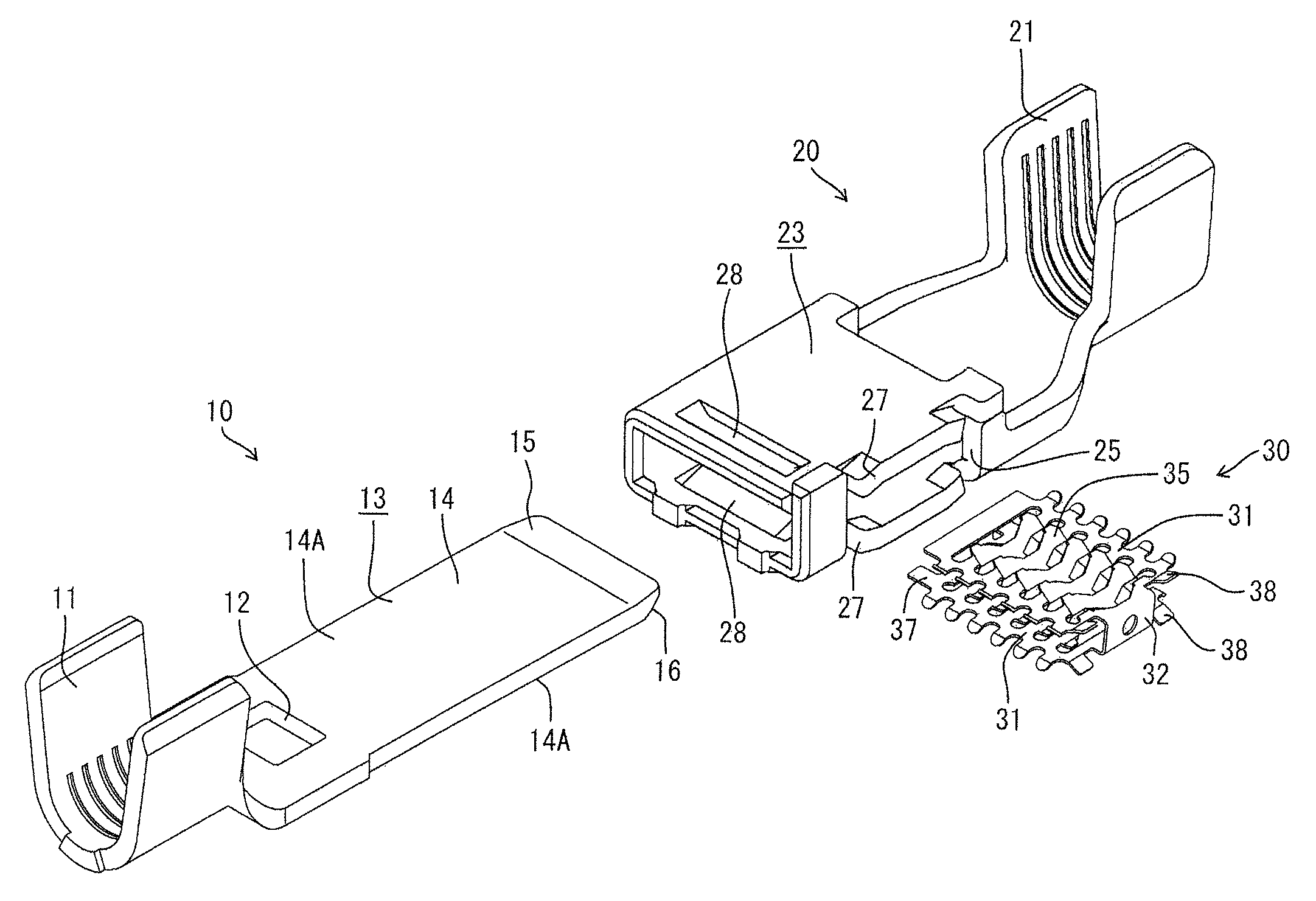
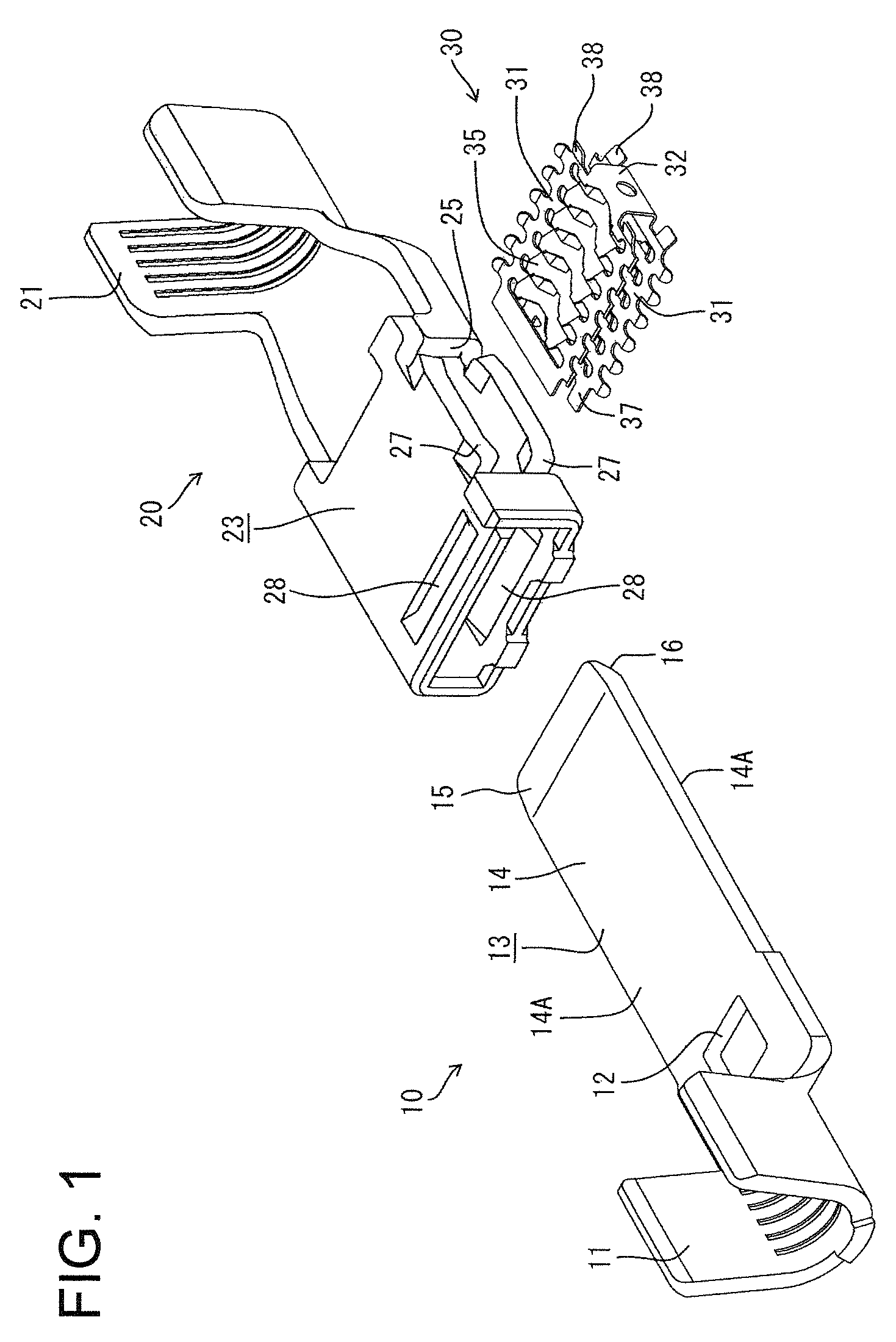
[0034]One particular embodiment of the present invention is described with reference to FIGS. 1 to 9.

[0035]In this embodiment is illustrated high-current terminal fittings used e.g. for a power supply line of an electric vehicle, a hybrid vehicle or the like. As shown in FIG. 1, a connecting structure includes a pair of a male terminal 10 and a female terminal 20 connectable to each other.

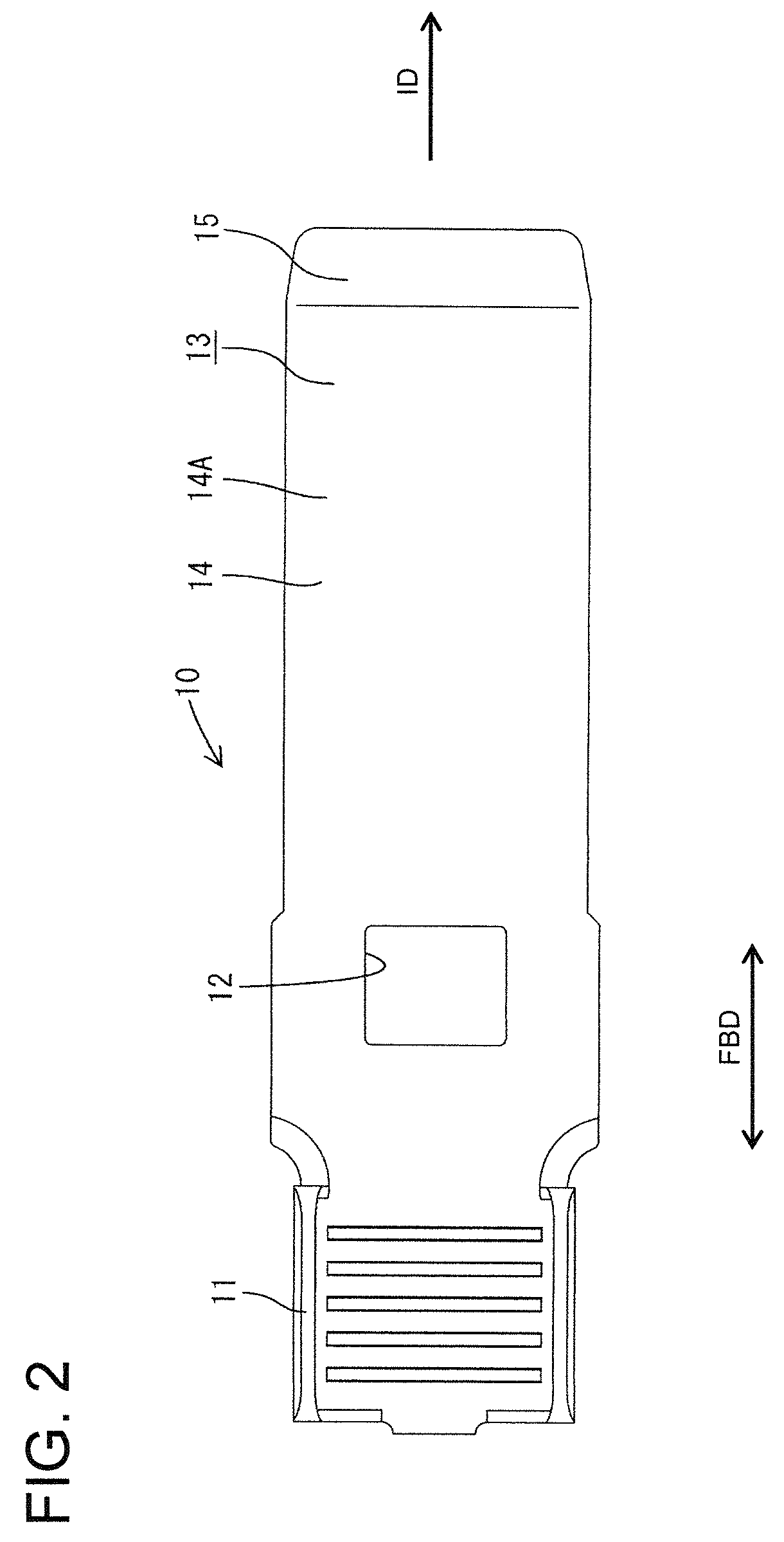
[0036]The male terminal 10 is formed by press-working a conductive (particularly metal) plate with good electrical conductivity such as copper alloy and having a relatively large thickness (e.g. 1.5 mm). A tab 13 in the form of a tongue piece particularly with a substantially constant width is formed before a wire connection portion to be connected to an unillustrated wire, the wire connection portion particularly comprising a barrel 11 to be crimped, bent or folded and connected to an end of a core of the unillustrated insulated wire. A base end portion of the tab 13 is slightly widened, and a loc...


PUM


Abstract

A connecting structure has a male terminal (10) including a tab (13) and a female terminal (20) including a rectangular connecting tube (23) that receives the tab (13). A louver spring (30) is housed in the connecting tube (23) and has two spaced apart contact piece rows (31) each including juxtaposed resilient contact pieces (35) with contact portions (36) facing each other. The tab (13) resiliently contacts the contact portions (36) by being inserted between the contact portions (36) while resiliently displacing the contact piece rows (31) at the opposite sides. Inclined surfaces (15, 16) are formed adjacent a tip of the tab (13) of the male terminal (10) to gradually thin the tab (13) toward the tip. The inclined surfaces (15, 16) are formed so that the positions of base end edges (15A, 16A) connected to flat surfaces 14A differ in forward and backward directions.

Description

BACKGROUND OF THE INVENTION[0001]1. Field of the Invention[0002]The invention relates to a connecting structure for male and female terminal fittings.[0003]2. Description of the Related Art[0004]U.S. Pat. No. 7,150,660 and FIG. 10 herein disclose a connecting structure for high-current terminal fittings. As shown in FIG. 10, this connecting structure has a male terminal 1 with a tab 2 in the form of a relatively thick tongue and a female terminal 3 with a rectangular connecting tube 4 into which the tab 2 is to be inserted. A louver spring 5 is housed in the connecting tube 4. The louver spring 5 has two contact piece rows each including a plurality of juxtaposed resilient contact pieces 6. The contact piece 6 has contact portions 6A arranged to face each other while being spaced apart. On the other hand, inclined surfaces 7 are formed on opposite surfaces of a tip of the tab 2 and taper the tip for guiding purposes.[0005]The tab 2 of the male terminal 1 is guided into the louver sp...

Claims


Application Information

Patent Timeline
Patent Type & Authority Patents(United States)
IPC IPC(8): H01R13/187
CPCH01R13/055H01R13/187H01R4/4881H01R13/113
Inventor MUKUNO, JUNICHI
Owner SUMITOMO WIRING SYST LTD
Why Eureka
Try Eureka