
Embedded power cable sensor array

a technology of power cable and sensor array, which is applied in the direction of cables, insulated conductors, instruments, etc., can solve the problems of limited current carrying capacity (sometimes referred to as “ampacity”) of electrical power cables, conservative design and unused capacity, and internal short-circuiting and cable failure. achieve the effect of reducing the curren

Active Publication Date: 2012-03-06
LOCKHEED MARTIN CORP
View PDF12 Cites 8 Cited by
  • Summary
  • Abstract
  • Description
  • Claims
  • Application Information

AI Technical Summary

Benefits of technology

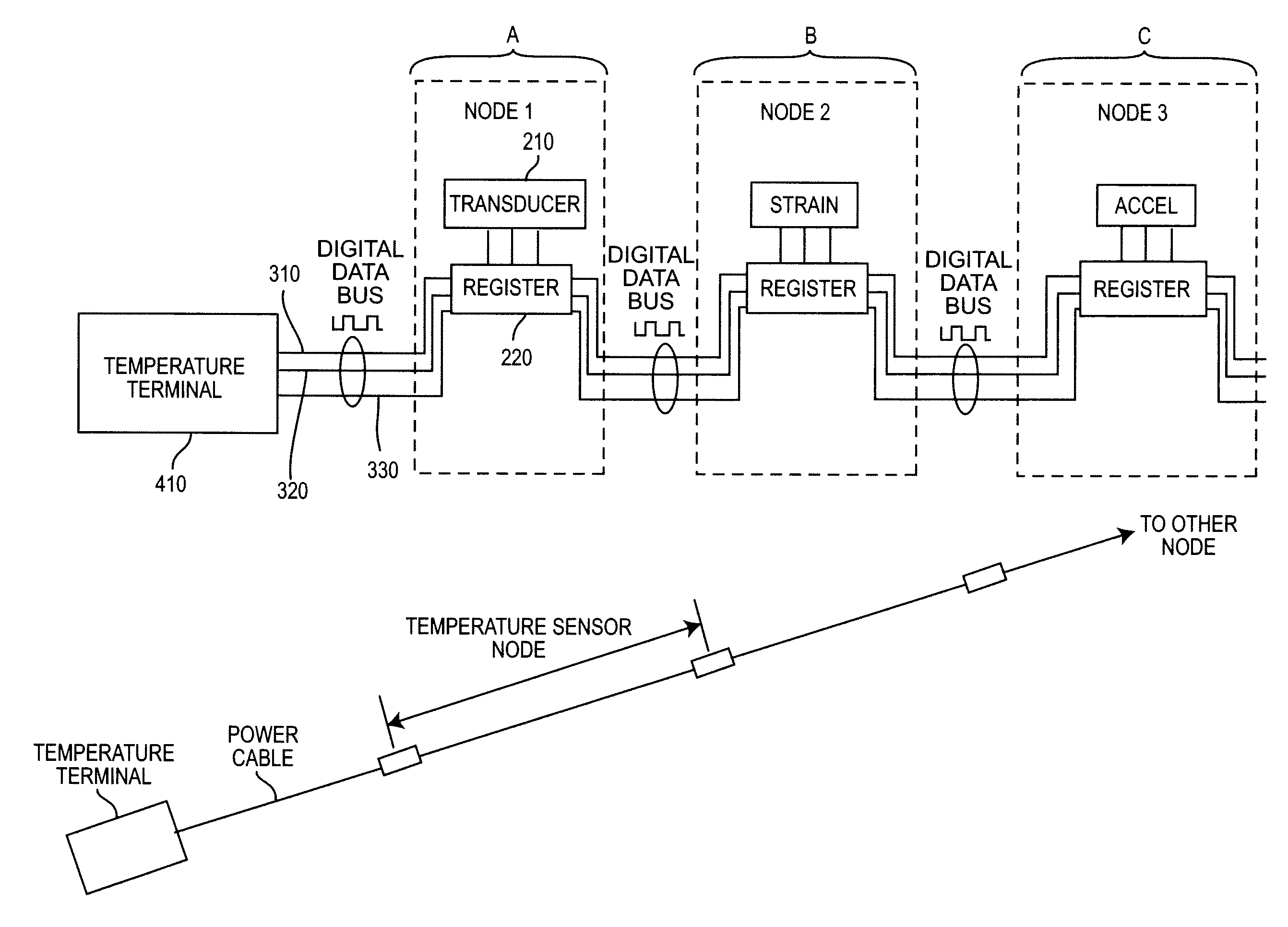
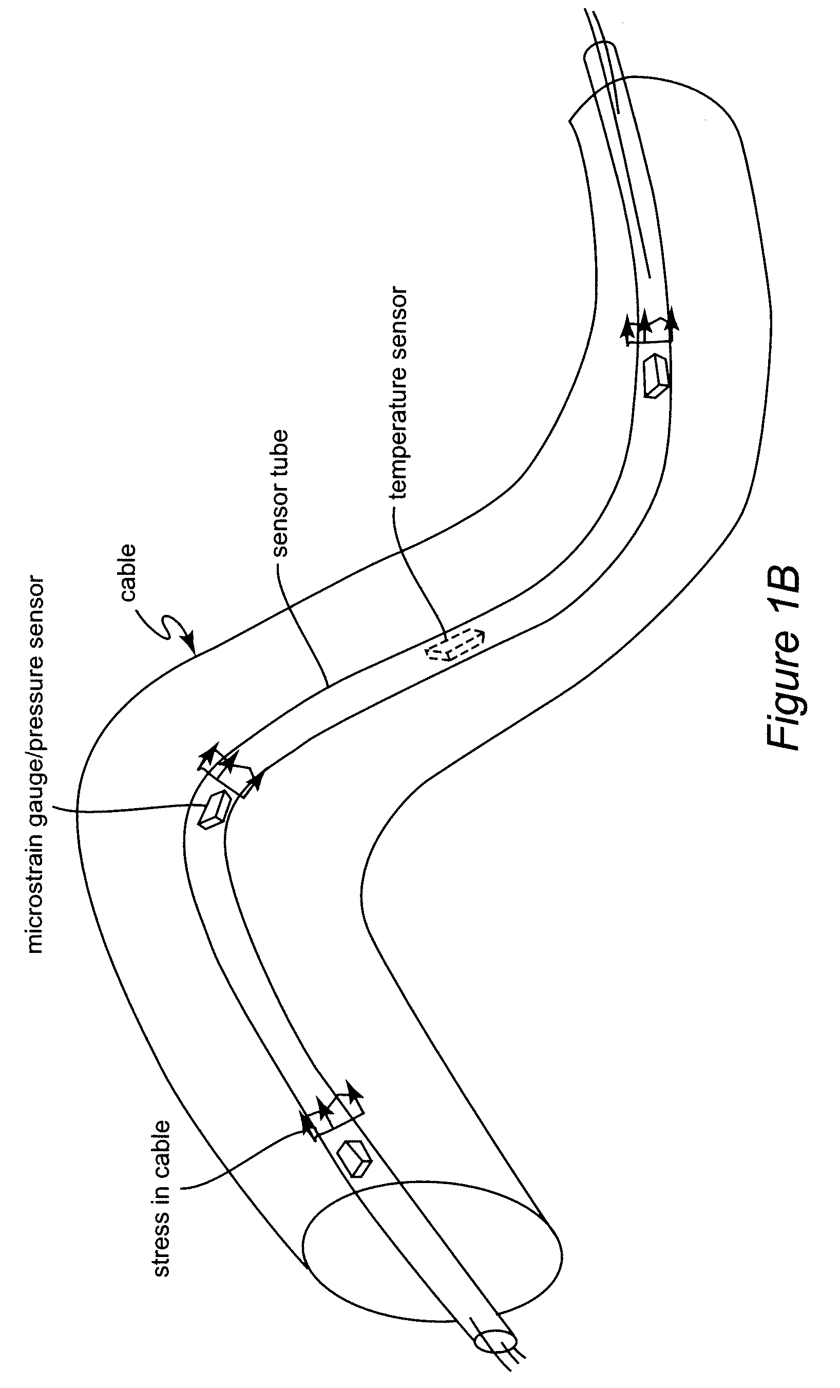
The present invention provides an electrical power delivery cable with embedded sensors that can monitor conditions at multiple locations within the cable. The sensors are connected by wires and powered by a tube containing the sensors. The sensor array can be installed by withdrawing wires from a preform, attaching terminals to the wires, and placing the sensor node and wires within the preform before sealing it. The invention also includes a method for managing risk of failure of the power delivery cable by monitoring various parameters such as temperature, acceleration, strain, material incursion, and magnetic field at multiple locations and reducing the electrical current in the cable accordingly.

Problems solved by technology

The current carrying capacity (sometimes referred to as “ampacity”) of electrical power cables is generally limited by allowable internal temperature rise due to heat generated by ohmic losses (sometimes referred to as “copper losses” regardless of the material from which the cable is made or, infrequently, “aluminum losses” or the like) due to electrical resistance in the cable and the ability of insulation to withstand such internal temperature rise.
Plastic insulation, in particular, which is in direct contact with a hot conductor may be partially or fully melted or may exhibit early loss of dielectric properties at high temperatures potentially causing internal short-circuiting and cable failure.
When standard cable designs having such built-in design margins cannot be used, particularly in high-performance applications such as where size or weight presents severe design constraints or so-called reeled applications where the cable is used while wound on a spool presenting many layers that retain and concentrate generated heat, predicting the temperature rise for all possible conditions can be difficult and can lead to conservative design and unused capacity with the corresponding costs and inefficiencies.
However, many more applications exist where the operating environment is much more variable and the cable design more critical and where built-in design margins cannot be observed.
It should be recognized that built-in design margins necessarily carry a cost and inherent inefficiency because the built-in design margins provide additional power-carrying capacity which is not used.
On the other hand, optimization of cable design essentially is an exercise in lowering design margins in regard to temperature, mechanical stresses including flexure, damage or the like and general cable operating conditions as much as possible, thus, in such circumstances as in this example, increasing the risk of failure offshore where the costs attributable to a failure can be enormous.
For many applications, the costs of providing excess but unused capacity or internal structures in electrical power delivery cables may significantly increase their size and weight or compromise other desirable properties such as flexibility and the risk and attendant costs of cable failure must be carefully managed.
Embedded fiber optic sensors are sometimes used to monitor cable temperature but such sensors are proprietary and subject to errors and other physical effects such as cable strain.
Determining cable temperature by a measurement of wire resistance is not practical since delivery of power must be interrupted to make the measurement and only provides an average temperature rise measurement for the entire cable while a common failure mode involves localized overheating in a possibly relatively short portion of a very long cable.

Method used


Image

  • Embedded power cable sensor array
  • Embedded power cable sensor array
  • Embedded power cable sensor array

Examples


Embodiment Construction

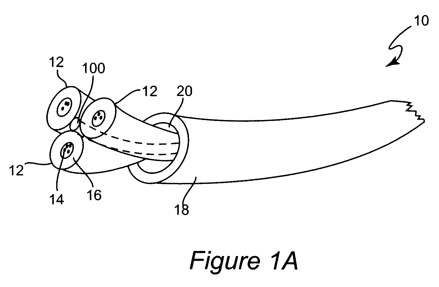
[0022]Referring now to the drawings, and more particularly to FIG. 1A, there is shown a section of an electrical power delivery cable 10 (hereinafter sometimes simply “cable”) with embedded sensors in accordance with the invention. The cable 10 includes a plurality (generally at least two but usually three, as shown, but as many such wires as desired may be included) of insulated wires 12 where the conductor 14 (which may be solid or comprised of a plurality of smaller strands) is generally of copper or aluminum, copper plated or sheathed aluminum or the like but the material chosen is of no importance to the successful practice of the invention. Each of these wires 12 includes electrical insulation layer 16 covering conductor 14 and the illustration thereof should be considered as including any additional structural feature(s) that may be desired for the particular application in which cable 10 is to be employed. Such additional structural features may include, without limitation, ...


PUM


Abstract

Semiconductor sensor chips are assembled with semiconductor communication chips to form sensor nodes which are wired together and placed in a tube preform which is sealed to form a tube containing an array of sensor nodes. The tube, resembling a wire in appearance, can then be assembled with power conductors to form a power delivery cable to allow monitoring of conditions within the cable at a plurality of spaced locations along the length of the cable so that the cable can be operated near or at its actual current carrying capacity which may be altered by ambient conditions and allowing management of risk of failure of the cable.

Description

BACKGROUND OF THE INVENTION[0001]1. Field of the Invention[0002]The present invention generally relates to the design, manufacture and operation of cables for delivery of electrical power and, more particularly, to power cables for special applications where power cables must be operated over a wide variety of environmental conditions or at or near actual power delivery capacity.[0003]2. Description of the Prior Art[0004]The variety of environments and circumstances where delivery of electrical power over a significant distance through a cable is required has expanded virtually without limit, particularly in recent years. Many such applications present relatively stable operating conditions and common characteristics of cable installation such as power distribution wiring in buildings, power lines, manufacturing facilities (where the environmental conditions may be particularly harsh but are largely consistent over time), appliances, computers (including large installations), instru...

Claims


Application Information

Patent Timeline
Patent Type & Authority Patents(United States)
IPC IPC(8): G08B13/12
CPCG01K13/00H01B7/324
Inventor PELLEN, ALAIN
Owner LOCKHEED MARTIN CORP
Learn More