Luminance level control device

a technology of level control and luminance, which is applied in the direction of color television details, television systems, instruments, etc., can solve the problems of visual recognition of unnatural changes in luminance, and achieve the effects of reducing power consumption, increasing video luminance, and increasing video luminan

Inactive Publication Date: 2012-03-06
PANASONIC CORP
View PDF23 Cites 12 Cited by
  • Summary
  • Abstract
  • Description
  • Claims
  • Application Information

AI Technical Summary

Benefits of technology

[0060]According to the present invention, a viewer can clearly recognize a scene change because a luminance level of video increases at the time of the scene change. In addition, the luminance level of video attenuates with an elapse of time after the scene change, so that power consumption is reduced. Since the scene change of video is not very frequent in general video, average power consumption can be sufficiently reduced.
[0061]Luminance and power consumption are temporally dispersed, thus enabling both high luminance display and reduction in power consumption.

Problems solved by technology

However, since the ABL characteristics cause the luminance level of the displayed video to be immediately controlled every time the average peak level changes, it has a disadvantage in that unnatural changes in luminance are visually recognized.

Method used


Image

  • Luminance level control device
  • Luminance level control device
  • Luminance level control device

Examples


first embodiment

[0082](1) First Embodiment

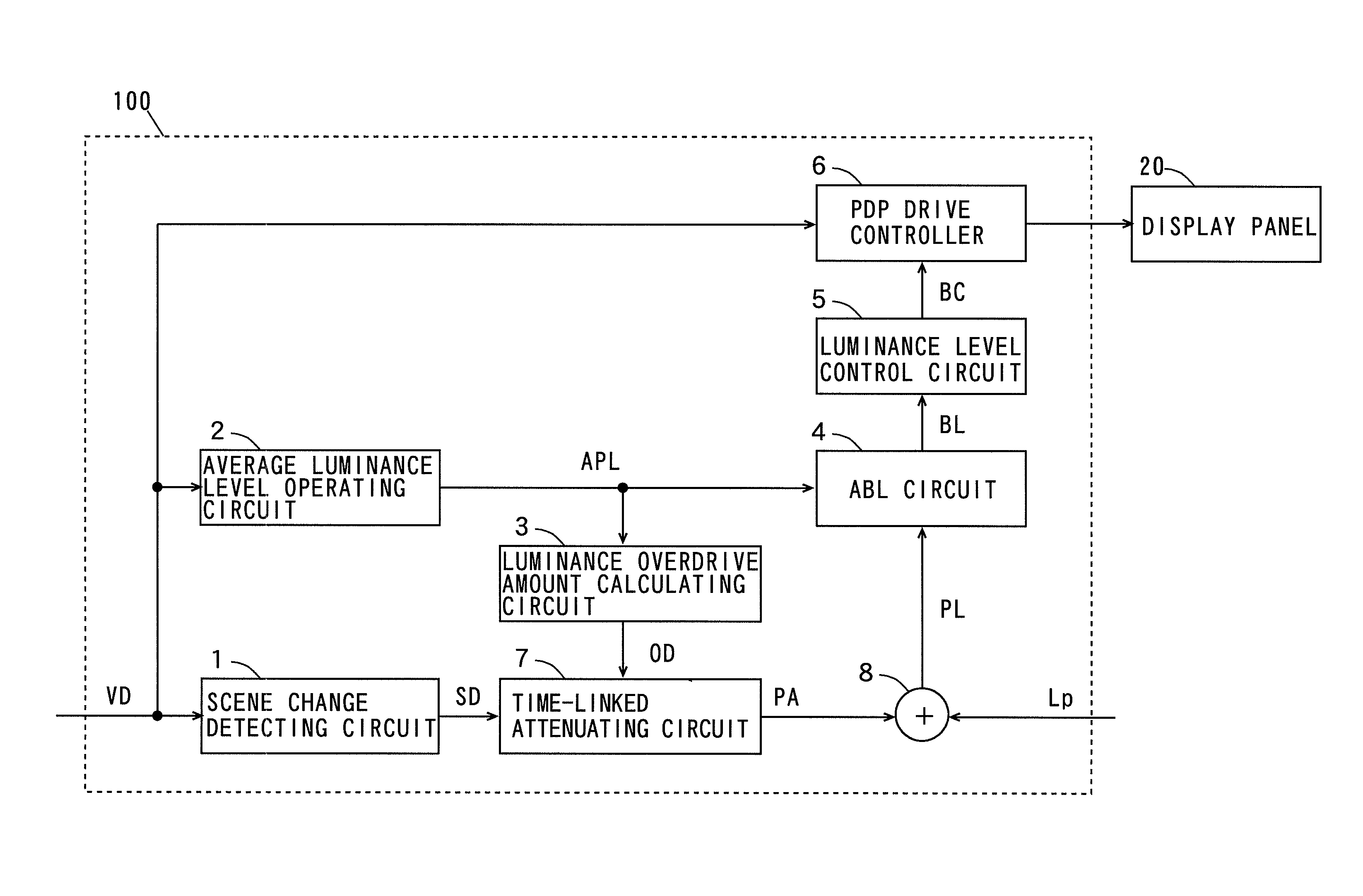
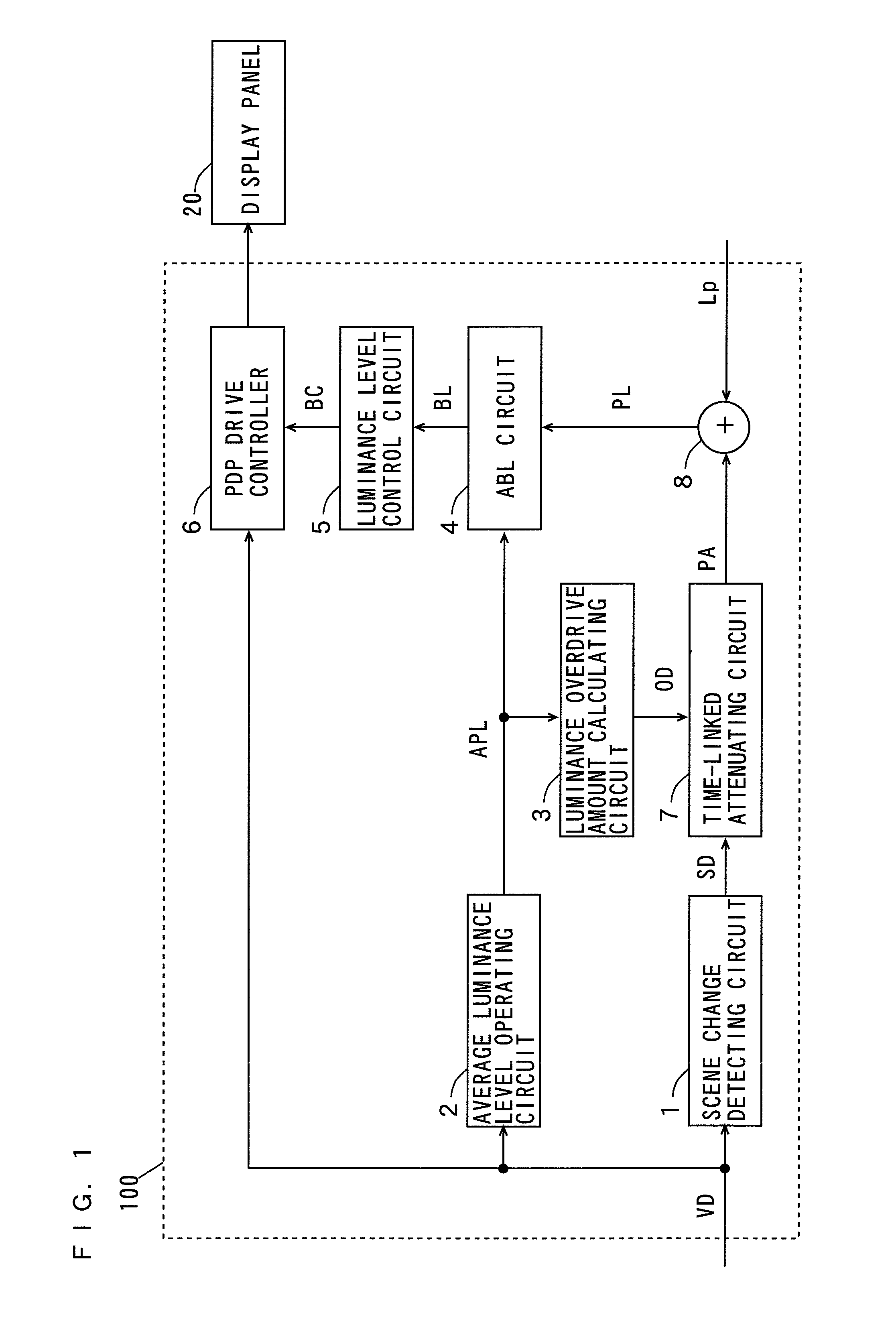
[0083]FIG. 1 is a block diagram showing the configuration of a luminance level control device according to a first embodiment of the present invention.

[0084]The luminance level control device 100 shown in FIG. 1 includes a scene change detecting circuit 1, an average luminance level operating circuit 2, a luminance overdrive amount calculating circuit 3, an automatically brightness limiting (hereinafter referred to as ABL) circuit 4, a luminance level control circuit 5, a plasma display panel (hereinafter referred to as PDP) drive controller 6, a time-linked attenuating circuit 7 and an adder 8. The luminance level control device 100 and a display panel 20 constitute a display device. In the present embodiment, the display panel 20 is a PDP.

[0085]A video signal VD representing video to be displayed is input to the scene change detecting circuit 1. The scene change detecting circuit 1 detects a scene change (switching of scenes) of the video based on changes...

second embodiment

[0124](2) Second Embodiment

[0125]FIG. 5 is a block diagram showing the configuration of a luminance level control device according to a second embodiment of the present invention.

[0126]The luminance level control device 100 shown in FIG. 5 is different from the luminance level control device 100 shown in FIG. 1 in that the scene change detecting circuit 1 detects the scene change based on the average luminance level APL output from the average luminance level operating circuit 2. Since the configuration and operation of other parts of the luminance level control device 100 of FIG. 5 is the same as the configuration and operation of the corresponding parts of the luminance level control device 100 of FIG. 1, the same portions are denoted by the same reference numerals and hence, the detailed description thereof is omitted.

[0127]The scene change detecting circuit 1 detects the scene change using the following method, for example. When a difference between the average luminance level o...

third embodiment

[0129](3) Third Embodiment

[0130]FIG. 6 is a block diagram showing the configuration of a luminance level control device according to a third embodiment of the present invention.

[0131]The luminance level control device 100 shown in FIG. 6 is different from the luminance level control device 100 shown in FIG. 1 in that a scene change number operating circuit 9 is further provided. Since the configuration and operation of other parts of the luminance level control device 100 of FIG. 6 is the same as the configuration and operation of the corresponding parts of the luminance level control device 100 of FIG. 1, the same portions are denoted by the same reference numerals and hence, the detailed description thereof is omitted.

[0132]The scene change detection signal SD output from the scene change detecting circuit 1 and the luminance overdrive amount OD output from the luminance overdrive amount calculating circuit 3 are supplied to the scene change number operating circuit 9.

[0133]The sc...


PUM


Abstract

A scene change detecting circuit (1) detects a scene change of video. An average luminance level operating circuit (2) calculates an average luminance level (APL) of a video signal (VD). A luminance overdrive amount calculating circuit (3) calculates a luminance overdrive amount (OD) based on the average luminance level (APL). A time-linked attenuating circuit (7) outputs a power consumption limit correction amount (PA) by attenuating the luminance overdrive amount (OD) with an elapse of time from a point in time of detecting the scene change. An adder (8) adds the power consumption limit correction amount (PA) and a reference power consumption limit value (Lp) to output the addition result as a power consumption limit amount (PL). An ABL circuit (4) calculates a luminance limit amount (BL) based on luminance limit characteristics, the average luminance level (APL) and the power consumption limit amount (PL). A luminance level control circuit (5) determines a display drive condition (BC) based on the luminance limit amount (BL). A PDP drive controller (6) drives a display panel (20) based on the video signal (VD) and the display driving condition (BC).

Description

TECHNICAL FIELD[0001]The present invention relates to a luminance level control device that controls a luminance level of video to be displayed on a display panel.BACKGROUND ART[0002]A plasma display panel includes a plurality of discharge cells arranged in the form of a matrix. In this plasma display panel, gas discharges are induced in the selected discharge cells, generating ultraviolet rays. The ultraviolet rays cause phosphors in the discharge cells to be excited, so that the discharge cells emit light. The number of times of discharges in the discharge cells per unit time, that is, the number of discharge sustain pulses applied to the discharge cells is controlled, thereby enabling display of luminance in multiple levels of gray.[0003]Generally, a sub-field method is employed as a driving system of the plasma display panel. In the sub-field method, one field corresponding to one screen of video is temporally divided into a plurality of sub-fields, and the ratio of a light emis...

Claims


Application Information

Patent Timeline
Patent Type & Authority Patents(United States)
IPC IPC(8): H04N5/57H04N5/14G09G3/28G09G3/288G09G3/291
CPCG09G3/288H04N5/147G09G2320/0242G09G2320/103G09G2330/021G09G2360/16
Inventor IWAKURA, NORIYUKITAKETANI, NOBUOYAMASHITA, TAKERUTOZAKI, SHOZOOOTOMO, TAKASHIYOSHINARI, HIROSHI
Owner PANASONIC CORP
Why Eureka
Try Eureka