Method and device for distortion correction in magnetic resonance imaging

a magnetic resonance imaging and distortion correction technology, applied in the field of magnetic resonance imaging (mri) technology, can solve the problems of many signals that overlap, geometric distortion, distortion in the mri process, etc., and achieve the effect of correcting movement distortion and geometric distortion in mri

Active Publication Date: 2012-03-06
SIEMENS HEALTHCARE GMBH
View PDF2 Cites 4 Cited by
  • Summary
  • Abstract
  • Description
  • Claims
  • Application Information

AI Technical Summary

Benefits of technology

[0009]One purpose of the present invention is to provide a method for correcting distortion in MRI which is able to effectively correct movement distortion and geometric distortion in MRI.
[0025]In summary, in the present invention, the k-space data are acquired in a number of readout directions, and are converted into a number of images. A pixel shift map is created and the geometric distortion in a number of images is respectively corrected according to the pixel shift map. The multiple geometric distortion-corrected images are combined. Since the movement distortion normally exists in the data readout direction, the acquisition of the k-space data in a number of readout directions can effectively correct the movement distortion. Moreover, correcting the geometric distortion in the images converted from data acquired in a number of data readout directions according to the pixel shift map can reduce the geometric distortion of the final image created from the combined data. The solution of the present invention corrects not only the movement distortion of MRI images, but also the geometric distortion of the MRI images.

Problems solved by technology

Due to the influence of various factors, distortion occurs in the MRI process.
In the case of a highly inhomogeneous magnetic field existing, many signals may overlap to create geometric distortion.
Many factors may cause inhomogeneity of a magnetic field, such as implanted metal devices and metal fixture is in the body of the patient.
Human body related distortions mainly include movement distortion, which is generated due the reason that the patient may lose patience and move his body during the prolonged MRI scanning process.
If the movement artifact is very serious, the image quality will be inferior and causes adverse effects on diagnosis.
Although PROPELLER technology can effectively correct the movement distortion, it can not correct the geometric distortion caused by inhomogeneity of the magnetic field or specific magnetization.

Method used


Image

  • Method and device for distortion correction in magnetic resonance imaging
  • Method and device for distortion correction in magnetic resonance imaging
  • Method and device for distortion correction in magnetic resonance imaging

Examples


embodiment 1

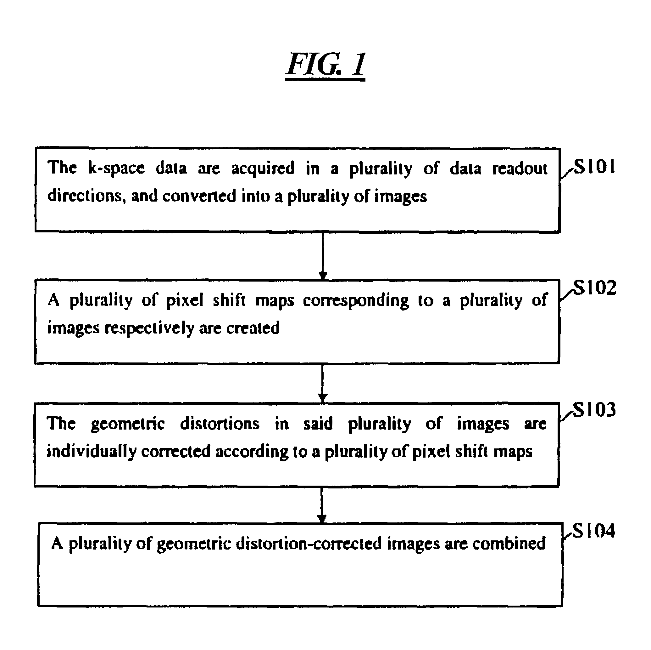
[0046]FIG. 2 is a flowchart of the method for correcting distortion in MRI used in embodiment 1 according to the present invention. As shown in FIG. 2, the correction of distortions in MRI mainly includes the following step:

[0047]step S201, that is, the PROPELLER technology is used to acquire the k-space data for imaging and converting the data into a number of images.

[0048]For a Turbo Spin Echo (TSE) sequence, since distortion only occurs in the data readout (RO) directions, if an imaging method uses one single RO direction, it will be difficult to recover these overlapping signals. The present invention employs the PROPELLER acquisition technology and can acquire data in a number of RO directions.

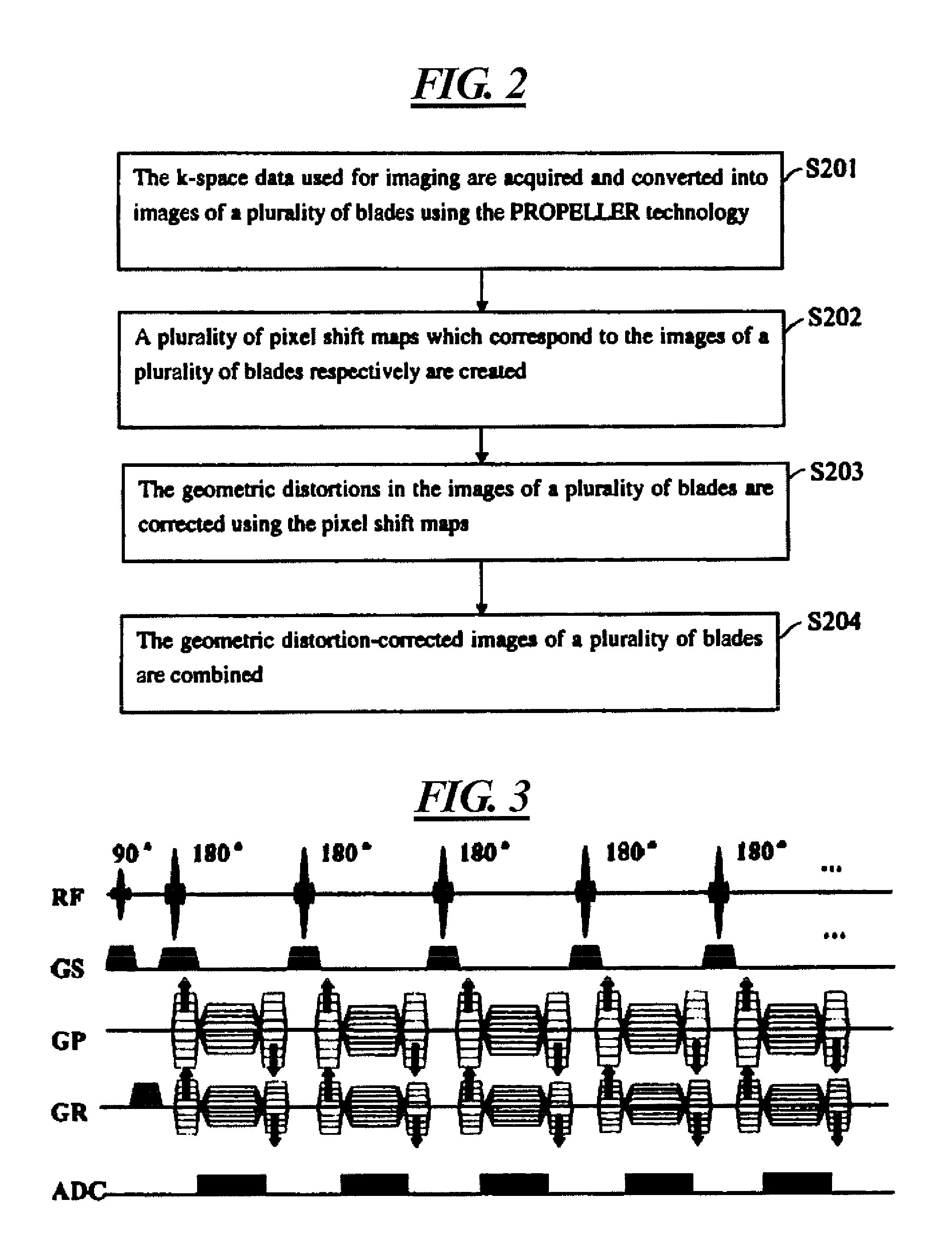
[0049]FIG. 3 is a schematic diagram of the TSE-based sequence in an echo train used in the PROPELLER technology. As shown in FIG. 3, in this embodiment, the traditional readout gradient and phase encoding gradient are combined to achieve the rotation of the actual encoding direction while...

embodiment 3

[0078]FIG. 8 shows the structure of the device for correcting distortion in MRI used in embodiment 3 according to the present invention. As shown in FIG. 8, said device comprises: an acquisition unit 801, a geometric distortion correction unit 802 and an image combination unit 803. In this case, the acquisition unit 801 acquires k-space data in a number of data readout directions and converts the data into a number of images; the geometric distortion correction unit 802 respectively creates a number of pixel shift maps corresponding to a number of images, and respectively corrects the geometric distortion in a number of images according to a number of pixel shift maps; the image combination unit 803 combines a number of geometric distortion-corrected images.

[0079]The geometric distortion correction unit 802 has a pixel shift map generation module 8021 and a geometric distortion correction module 8022. In this case, the pixel shift map generation module 8021 creates a number of pixel...

embodiment 4

[0081]FIG. 9 shows the structure of the device for correcting distortion in MRI used in embodiment 4 according to the present invention. As shown in FIG. 9, this device has an acquisition unit 901, a geometric distortion correction unit 902, an image combination unit 903 and a severely distorted region replacement unit 904. In this case, the acquisition unit 901, geometric distortion correction unit 902 and image combination unit 903 have the same functions as that of the acquisition unit 801, geometric distortion correction unit 802 and image combination unit 803, respectively.

[0082]The severely distorted region replacement unit 904, located between the geometric distortion correction unit 902 and the image combination unit 903, determines whether there is a severely distorted region in the number of geometric distortion-corrected images, and replaces the pixel value in the severely distorted region with the pixel value in the corresponding region of other images from a number of i...


PUM


Abstract

In a method and device for correcting distortion in MRI, k-space data are acquired in a number of data readout directions, the data are converted into a number of images, and a corresponding pixel shift map is generated for each image. The geometric distortion in the corresponding image is corrected according to the pixel shift map, and then all geometric distortion-corrected images are combined. Since movement distortion normally exists in the data readout direction, collecting the k-space data from a number of data readout directions can effectively correct movement distortion. Moreover, correcting the geometric distortion for the images converted from data acquired in a number of data readout directions according to the pixel shift map can reduce the geometric distortion of the final image generated from combination of images. The method and device correct not only movement distortion of MRI images, but also geometric distortion of MRI images.

Description

BACKGROUND OF THE INVENTION[0001]1. Field of the Invention[0002]The present invention relates to magnetic resonance imaging (MRI) technology, and more particularly, to a method and device for correcting distortion in MRI.[0003]2. Description of the Prior Art[0004]Due to the influence of various factors, distortion occurs in the MRI process. By their sources, the distortions which are normally found in MRI can principally be divided into magnetic field related distortion and human body related distortion.[0005]The magnetic field related distortion is mainly attributable to the inhomogeneous magnetic field, especially the geometric distortion induced by inhomogeneity of the primary magnetic field. In the case of a highly inhomogeneous magnetic field existing, many signals may overlap to create geometric distortion. Many factors may cause inhomogeneity of a magnetic field, such as implanted metal devices and metal fixture is in the body of the patient.[0006]Human body related distortio...

Claims


Application Information

Patent Timeline
Patent Type & Authority Patents(United States)
IPC IPC(8): G06K9/00
CPCG01R33/4824G01R33/56509G01R33/56563G01R33/5617
Inventor LI, GUO BIN
Owner SIEMENS HEALTHCARE GMBH
Why Eureka
Try Eureka