Deflection yoke for cathode ray tube

Inactive Publication Date: 2006-08-17
SAMSUNG SDI CO LTD
View PDF9 Cites 0 Cited by
  • Summary
  • Abstract
  • Description
  • Claims
  • Application Information

AI Technical Summary

Benefits of technology

[0015] The present invention provides a deflection yoke for a cathode ray tube. The deflection yoke has a correction unit and improves assembly and productivity to effectively control the correction during processing.
[0016] The deflection yoke for the cathode ray tube includes a horizontal deflection coil located next to the outer circumference of a funnel to generate a horizontal deflection magnetic field, and a vertical deflection coil installed at the outer circumference of the funnel to generate a vertical deflection magnetic field. The vertical deflection coil is insulated from the horizontal deflection coil. A ferrite core is located next to the vertical deflection coil to reduce the loss of magnetic force generated from the horizontal and the vertical deflection coils, and to enhance the magnetic efficiency. A correction unit is spaced apart from the horizontal deflection coil by a predetermined distance to correct geometric distortion of the vertical and the horizontal deflection magnetic fields.

Problems solved by technology

However, when the GD correction unit is mounted in the case or chassis, it is spaced apart from the location of the deflection yoke (the outer circumference of the funnel), and hence, the desired correction effect is not obtained satisfactorily.
Furthermore, in the manufacturing process, it is impossible to control the amount of correction of the GD correction unit before assembling the case or chassis.
Accordingly, if the units are defective, the resulting loss is substantial.

Method used


Image

  • Deflection yoke for cathode ray tube
  • Deflection yoke for cathode ray tube
  • Deflection yoke for cathode ray tube

Examples


Embodiment Construction

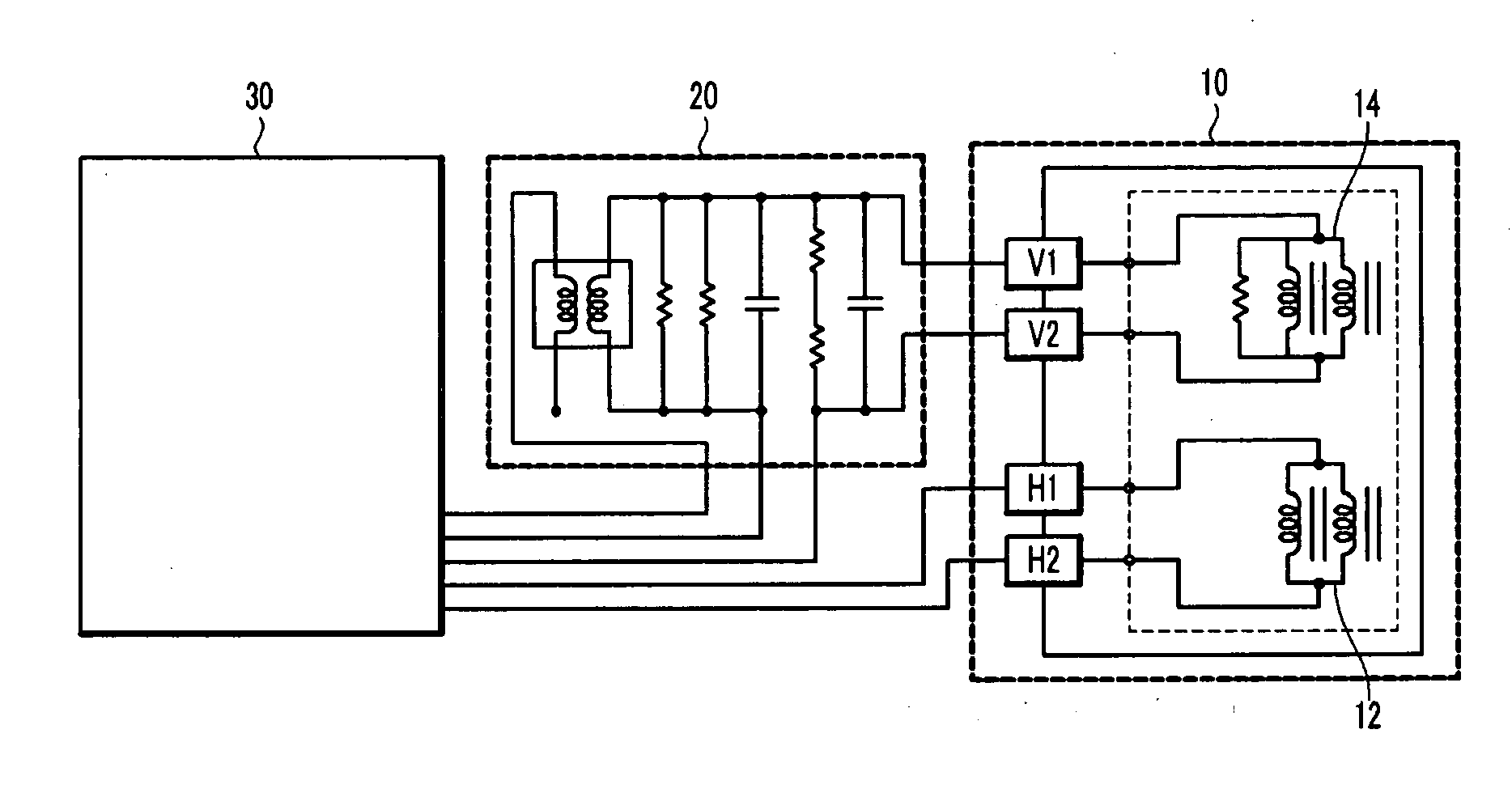
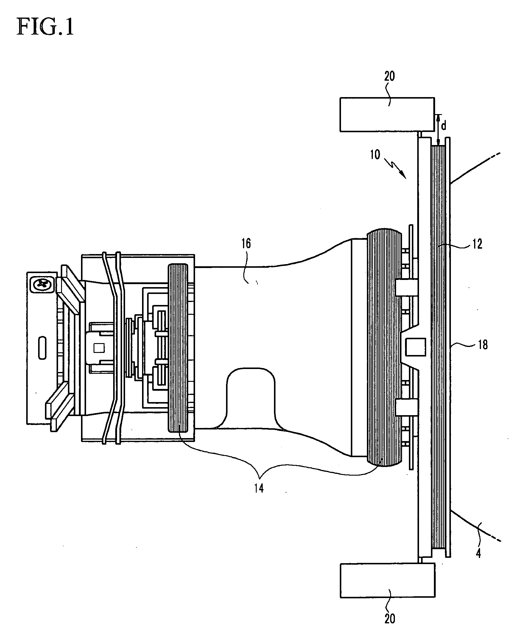
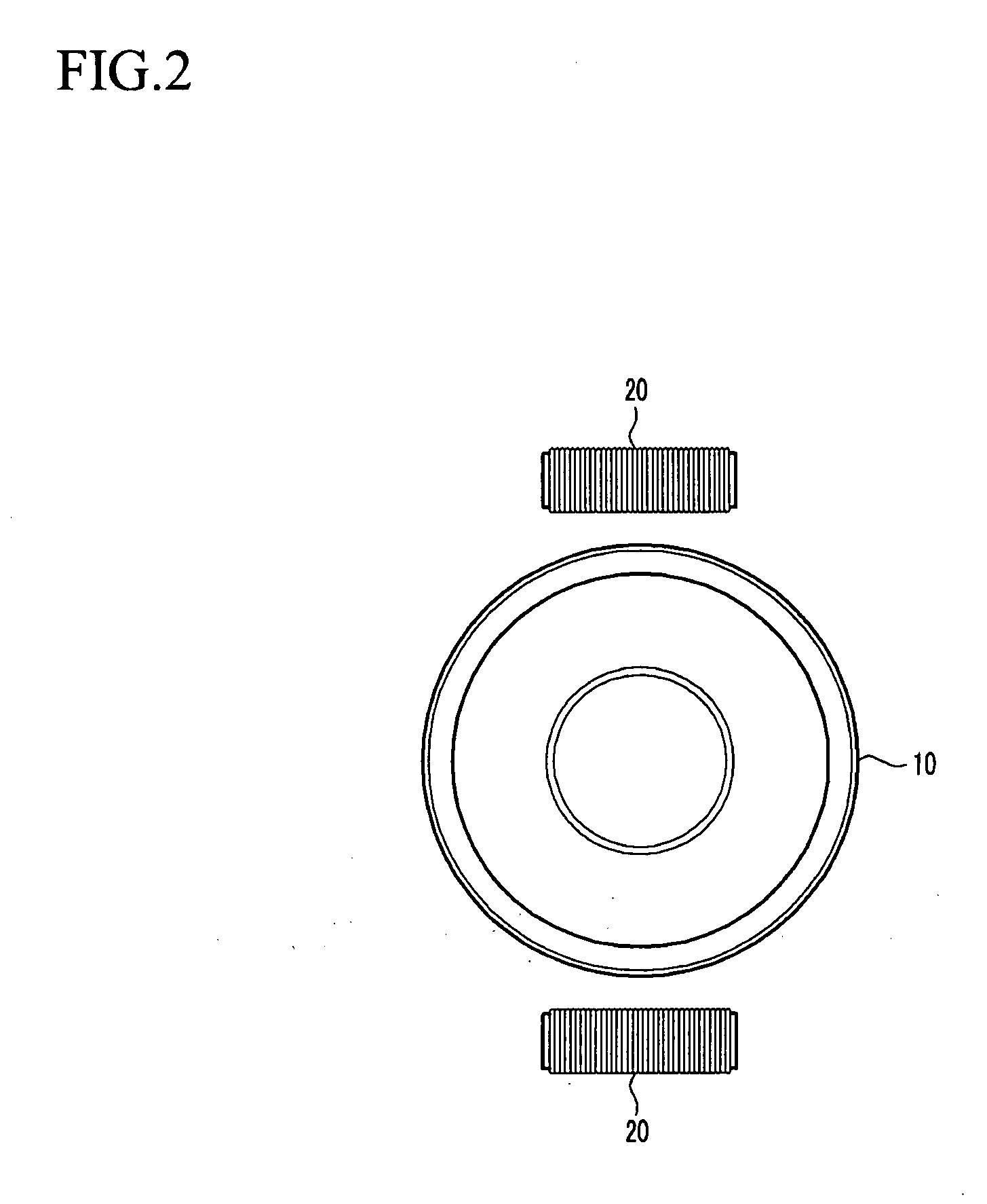
[0025]FIGS. 1 and 2 illustrate a deflection yoke for a cathode ray tube according to an embodiment of the present invention. As shown in FIGS. 1 and 2, the deflection yoke includes a horizontal deflection coil 12 located close (next) to the outer circumference of the funnel 4 to generate a horizontal deflection magnetic field, and a vertical deflection coil 14 provided on the outer circumference of the funnel 4 to generate a vertical deflection magnetic field. The vertical deflection coil 14 is insulated from the horizontal deflection coil 12. A ferrite core 16 is located close to the vertical deflection coil 14 to reduce a loss of the magnetic force generated due to the horizontal and the vertical deflection coils 12 and 14, and enhance the magnetic efficiency. A correction unit 20 is spaced apart from the horizontal deflection coil 12 by a predetermined distance d to correct a geometric distortion in the vertical and the horizontal magnetic fields generated due to the vertical and...


PUM


Abstract

A deflection yoke for a cathode ray tube improves assembly and productivity and enables effective control of magnetic field corrections during device processing. The deflection yoke includes a horizontal deflection coil located next to the outer circumference of a funnel to generate a horizontal magnetic field, and a vertical deflection coil installed at the outer circumference of the funnel to generate a vertical deflection magnetic field. The vertical deflection coil is insulated from the horizontal deflection coil. A ferrite core is located close to the vertical deflection coil to reduce the loss in the magnetic force generated from the horizontal and vertical deflection coils, and to enhance their magnetic efficiency. A correction unit is spaced apart from the horizontal deflection coil by a predetermined distance to correct a geometric distortion of the vertical and the horizontal deflection magnetic fields that is generated due to the vertical and horizontal deflection coils.

Description

CROSS-REFERENCE TO RELATED APPLICATION [0001] This application claims priority to and the benefit of Korean Patent Application No. 10-2005-0012655 filed in the Korean Intellectual Property Office on Feb. 16, 2005, the entire content of which is incorporated herein by reference. BACKGROUND OF THE INVENTION [0002] 1. Field of the Invention [0003] The present invention relates to a deflection yoke for a cathode ray tube, and in particular, to a deflection yoke having a correction unit to improve the assembly and productivity thereof, and to effectively control corrections during processing. [0004] 2. Description of Related Art [0005] Generally, a cathode ray tube includes a neck with an electron gun mounted therein, a funnel with a deflection yoke mounted on the outer circumference thereof, and a panel with a shadow mask and a phosphor film. Electron beams emitted from the electron gun are deflected by a deflection magnetic field generated from the deflection yoke. The deflected electr...

Claims


Application Information

Patent Timeline
IPC IPC(8): H01J29/70
CPCH01J29/701A47J37/1247A47J37/1266A47J37/1271A47J37/1276
Inventor KIM, DO-NYUNLEE, RAN-JINAM, JE-WOOKBYON, CHANG-RYONKIM, HOO-DEUKKIM, MOON-JINLEE, SANG-HOON
Owner SAMSUNG SDI CO LTD
Why Eureka
Try Eureka