Dental mirror with mirror-cleaning suction

a technology of mirrors and dentins, applied in the field of dentins with suction, can solve the problems of robbery of suction, ineffective port in the rearward half of the periphery of the reflective surface, and common obscurement of dentins, etc., and achieve the effect of convenient us

Active Publication Date: 2012-03-13
EMMONS III DONALD L
View PDF7 Cites 10 Cited by
  • Summary
  • Abstract
  • Description
  • Claims
  • Application Information

AI Technical Summary

Benefits of technology

[0007]These objects are achieved first by a typically circular self-cleaning dental mirror that maintains the mirror reflective surface unobstructed during a dental procedure by drawing air across the reflective surface and second by providing for removal and replacement of just the

Problems solved by technology

Dental mirrors commonly become obscured by water introduced by another dental implement or by patient saliva or by debris ancillary to the dental procedure.
The reflective surface of mirrors also frequently gets scratched or otherwise damaged.
It has

Method used


Image

  • Dental mirror with mirror-cleaning suction
  • Dental mirror with mirror-cleaning suction
  • Dental mirror with mirror-cleaning suction

Examples


Embodiment Construction

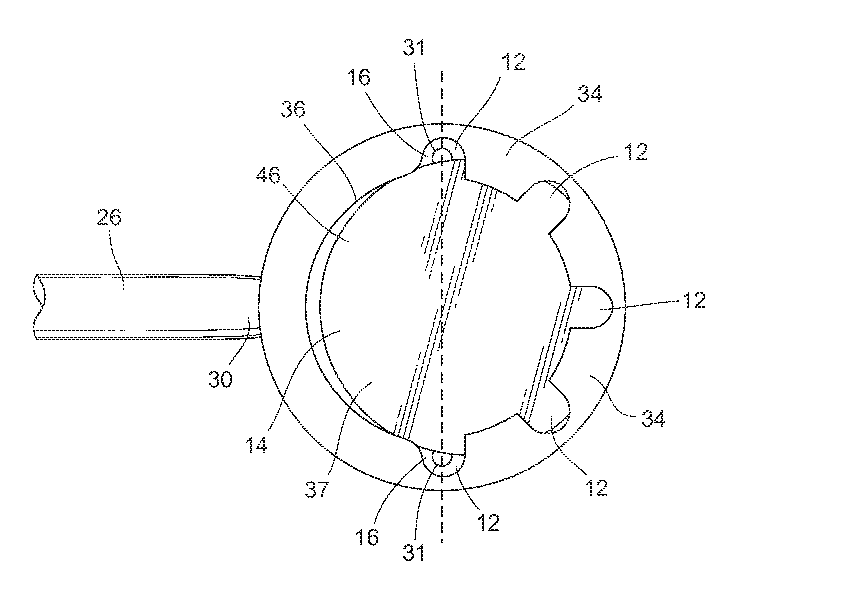
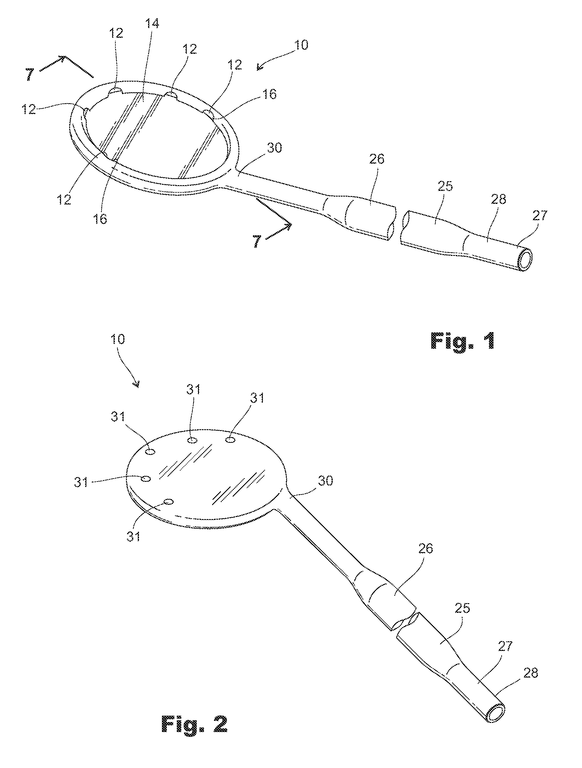
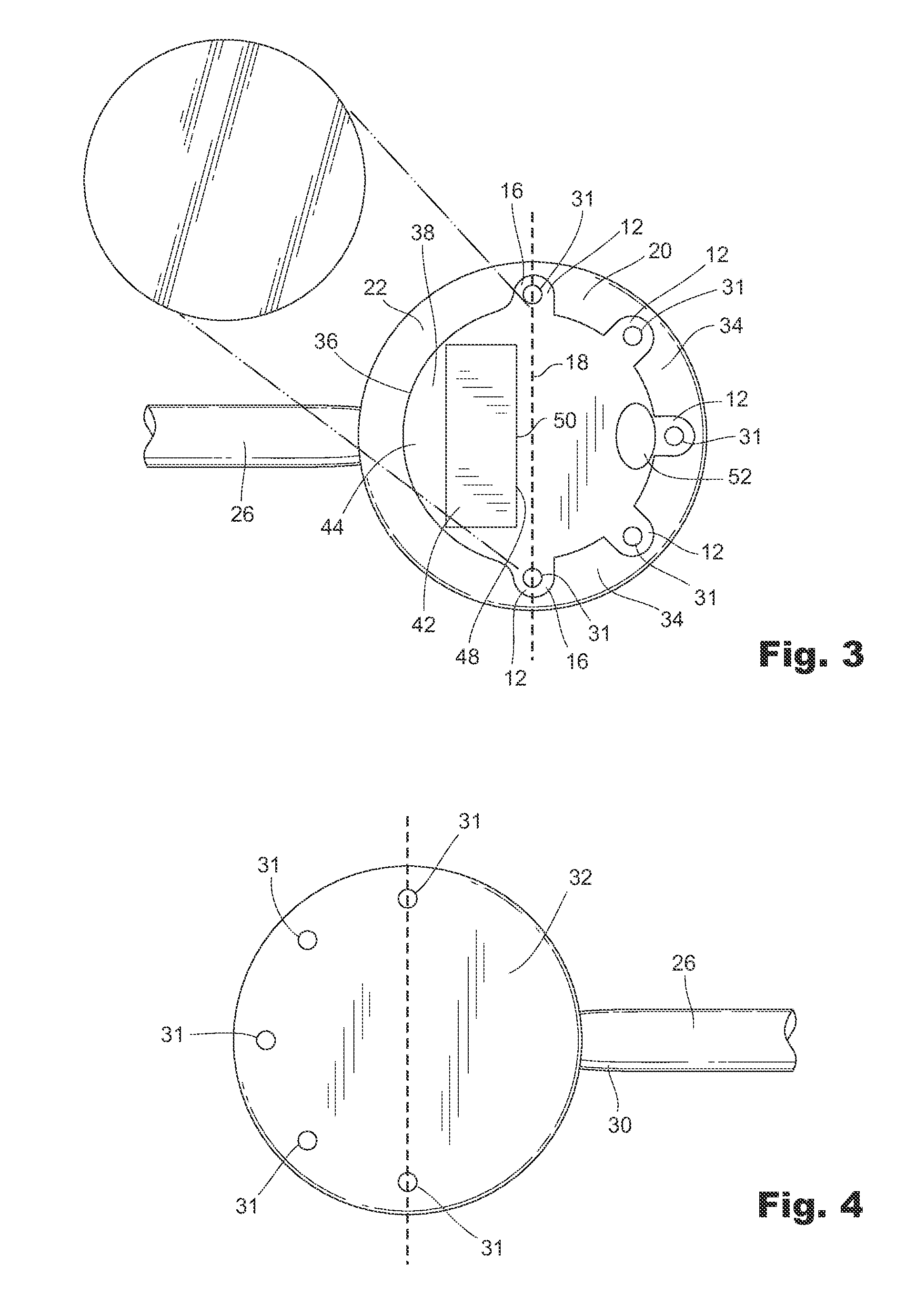
[0023]The dental mirror 10 of the present invention includes mirror cleaning suction through a plurality of suction ports 12 on the periphery of the mirror's reflective surface 14. The ports 12 are spaced apart about a forward half of the mirror 10 with the suction ports 12 directed across the reflective surface 14, two of which also function as a pair of access ports 16 whose centers lie on a diameter 18 dividing mirror forward and rearward halves 20, 22.

[0024]A handle 26 extends from central in the rearward half 22 of the mirror 10 and provides fluid communication through the handle 26 between a suction device (not shown) connectable to a handle first end 28. Dental offices employ low and high speed suction vacuum lines. Small vacuum lines of about 0.25-inch diameter and large vacuum lines of about 7 / 16-inch diameter are used with the respective low and high speed suction vacuum lines to assure implements are correctly connected to the required suction line. The handle 26 accommod...


PUM


Abstract

A dental suction mirror with a plurality of suction ports on the periphery of the reflective surface spaced apart substantially about a forward half of the mirror with the ports directed across the reflective surface. The mirror also includes a plurality of lower suction holes directed out of the cavity downward from a bottom of the mirror. The reflective surface of the mirror is replaceable.

Description

BACKGROUND[0001]1. Field of the Invention[0002]This invention pertains to dental implements, and more specifically to a dental mirror with suction ports on the periphery of the mirror that cleans the mirror reflective surface by drawing air across the reflective surface during a dental procedure.[0003]2. Prior Art[0004]It is known to have dental mirrors to facilitate various treatments by the dentist or hygienist. It is also known to have dental mirrors that include suction ports that draw fluids and debris through the mirror and out the mirror handle, allowing the dentist or hygienist to proceed without the involvement of an assistant using a separate suction hose and without a suction hose that hooks on the user's mouth. Suction ports in these mirrors previously have been directed radially outward from the mirror from a circular mirror, such as described in U.S. Pat. No. 5,813,856 by Lee, to draw from the patient's mouth but with no function of keeping the reflective surface of th...

Claims


Application Information

Patent Timeline
IPC IPC(8): A61B1/24
CPCA61B1/00094A61B1/00096A61B1/00101A61B1/126A61B1/247A61C17/088
Inventor EMMONS, III, DONALD L.
Owner EMMONS III DONALD L
Why Eureka
Try Eureka